Flow meter

A flowmeter and counter technology, applied in the field of flowmeters, can solve problems such as being easily affected by dirt accumulation

Pending Publication Date: 2022-02-22
WLKA ALEXANDER WIEGAND SE & CO KG
View PDF2 Cites 0 Cited by
  • Summary
  • Abstract
  • Description
  • Claims
  • Application Information

AI Technical Summary

Problems solved by technology

The delicate channel structure with integrated MEMS sensor mechanism is however susceptible to dirt buildup, so such flowmeters are practically only suitable for use in cleaner gaseous media

Method used


Image

  • Flow meter
  • Flow meter
  • Flow meter

Examples


Embodiment Construction

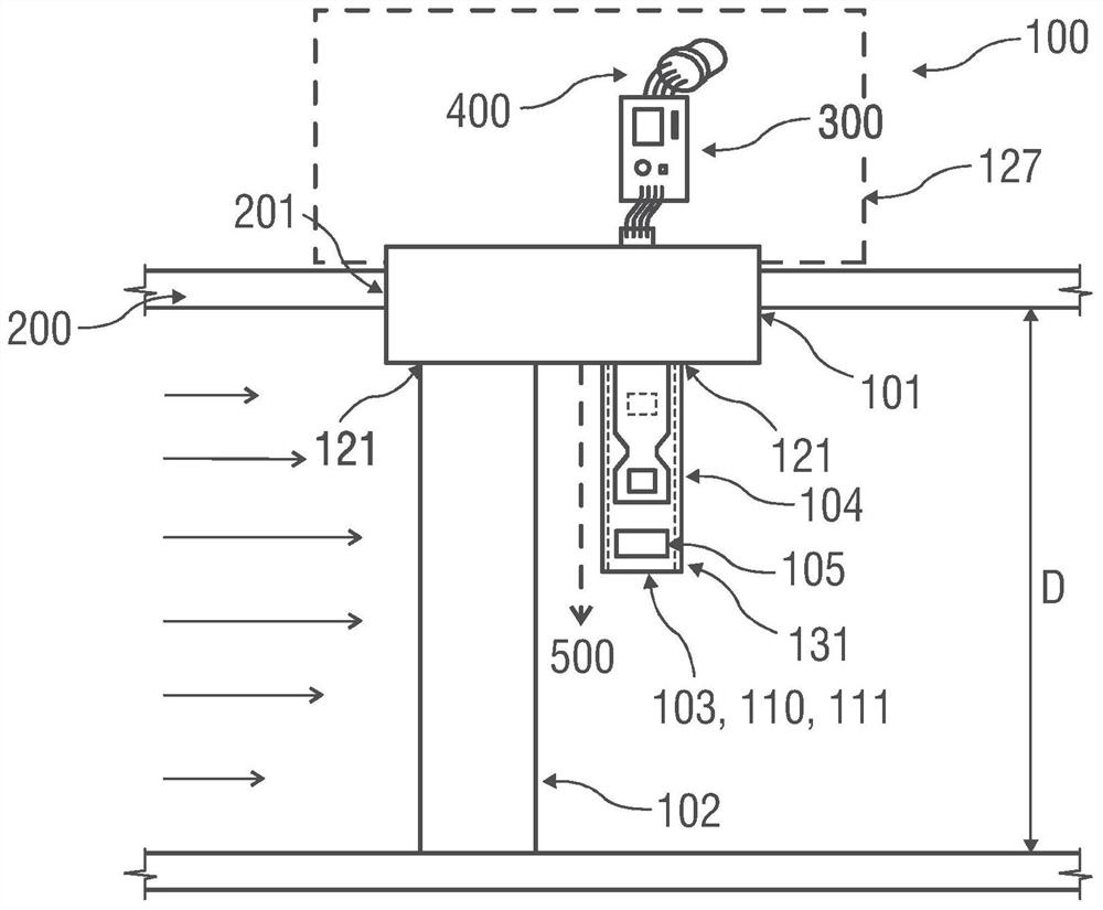
[0120] figure 1 An exemplary embodiment of a flow meter 100 is shown which combines the features of several previously described possible variants of the flow meter 100 according to the invention.

[0121] The flow meter 100 is arranged at a measurement position 201 of the medium pipeline 200 . The flow rate profile of the fluid in the medium line 200 is schematically shown by the arrow on the left side of the medium line 200 .

[0122] The flow meter 100 comprises a sensor base 101, an obstruction body 102 and a sensor body 103 having a support body member 110, a base assembly 111, a gas flow meter-sensor unit 104 and a vortex counter-sensor unit 105, the immersion of the obstruction body The depth substantially corresponds to the diameter D of the medium pipe 200 . In this case, vortex counter sensor unit 105 is arranged in the region of end section 131 of sensor body 103 . The immersion depth of the sensor body 103 corresponds at least substantially to half the diameter...


PUM


Abstract

The invention relates to a flow meter (100) for determining a fluid flow rate in a media line (200). A flow meter (100) includes: a sensor base (101) including a barrier body (102) and a sensor body (103); an electronic unit (300) and a signal interface (400), wherein the obstruction (102) is arranged substantially upstream of the sensor body (103) in the flow direction. The sensor body (103) comprises a support body piece (110) and a base assembly (111). The substrate assembly has at least one ceramic substrate (108, 109). The gas flow meter-sensor unit (104) and the vortex counter-sensor unit (105) are provided on the base assembly (111).

Description

technical field [0001] The invention relates to a flow meter for determining the flow velocity of a fluid in a medium pipeline. [0002] The invention also relates to a method for installing such a flow meter in a medium line. Background technique [0003] Measuring devices for determining the flow rate of liquid fluids or gaseous fluids in media lines already exist in the field of flow measurement. These measuring devices are hereinafter referred to as flow meters. [0004] Flow meters in the prior art utilize different operating principles which are each advantageous in a particular application. [0005] Furthermore, so-called vortex flowmeters, which are also called vortex counters, are useful in that the boundary layer, on a barrier to the flow around which is also called a barrier, is shed from a certain flow velocity with an altered direction of rotation, forming a so-called Karman vortex street. The frequency of the eddy current shedding can be detected by means o...

Claims


Application Information

Patent Timeline
Patent Type & Authority Applications(China)
IPC IPC(8): G01F1/32G01F1/69
CPCG01F1/69G01F1/3259G01F1/3266G01F1/684G01F7/00G01F1/325G01F1/3273
Inventor 法比安·菲弗安德烈·罗瑟尤尔根·普莱尔亚历山大·威尔
Owner WLKA ALEXANDER WIEGAND SE & CO KG
Why Eureka
Try Eureka