
Sectional type oil nozzle and optimization design method thereof

A segmented, fuel injector technology, applied in neural learning methods, computer-aided design, design optimization/simulation, etc., to enhance turbulent flow characteristics, avoid cavitation damage, and facilitate accurate predictions

Pending Publication Date: 2022-02-18
JIANGSU UNIV
View PDF0 Cites 4 Cited by
  • Summary
  • Abstract
  • Description
  • Claims
  • Application Information

AI Technical Summary

Problems solved by technology

[0006] The purpose of the present invention is to provide a segmented fuel injector for fuel injection system and its optimization design method in view of the existing problems and deficiencies of the current fuel injector. It will not have any impact on the internal structure of the needle valve and the needle valve body, and effectively suppress the geometric cavitation in the injection hole section, strengthen the turbulent flow disturbance in the turbulence cavity and the bell mouth section, and promote the jet flow breakage and flow downstream of the injection nozzle. Mixing of oil and gas to reduce soot emission while improving combustion thermal efficiency

Method used


Image

  • Sectional type oil nozzle and optimization design method thereof
  • Sectional type oil nozzle and optimization design method thereof
  • Sectional type oil nozzle and optimization design method thereof

Examples


Embodiment Construction

[0041] In order to make the object, technical solution and advantages of the present invention clearer, the present invention will be further described in detail below in conjunction with the accompanying drawings and embodiments. It should be understood that the specific embodiments described here are only used to explain the present invention, not to limit the present invention.

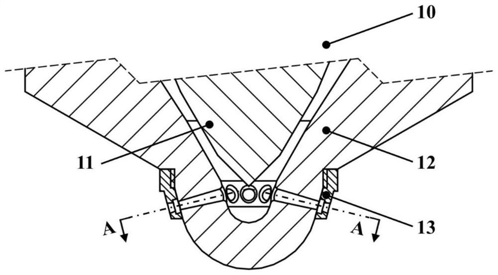
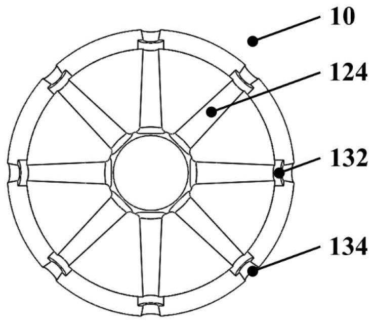
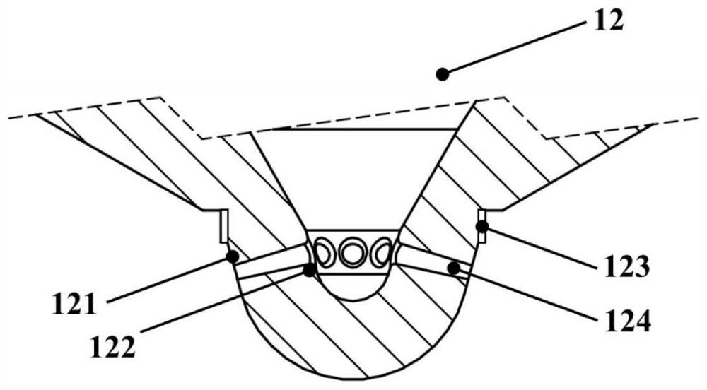
[0042] A fuel injector for a fuel injection system provided in this embodiment, such as figure 1 , 2 As shown in and 3 , the improved segmented fuel injector 10 includes a needle valve 11 , a needle valve body 12 and a spoiler collar 13 . The needle valve 11 is located inside the needle valve body 12, and the needle valve 11 and the needle valve body 12 are coaxially matched. The bottom of the needle valve body 12 outside is a hemisphere, and the needle valve body 12 sidewall above the hemisphere is provided with an annular platform, the outside of this annular platform is processed with external...


PUM


Abstract

The invention discloses a sectional type oil nozzle and an optimization design method thereof. The oil nozzle comprises a needle valve, a needle valve body and a turbulent flow ring sleeve, wherein the needle valve and the needle valve body are coaxially matched, and the needle valve is located in the needle valve body; oil injection holes which are evenly distributed in the circumferential direction are formed in the needle valve body, turbulent flow concave cavities and flare openings are formed in the turbulent flow ring sleeve, and the turbulent flow concave cavities, the flare openings and the oil injection holes are coaxially distributed and are the same in number; and the turbulent flow ring sleeve is in threaded connection with the needle valve body, adjacent boundaries are consistent in shape and are in close fit, and the structure can enhance the circulation performance and the atomization performance of the oil nozzle at the same time. Based on the sectional type oil nozzle, a transparent oil nozzle internal flow and spray visualization experiment table is established; factors, levels and indexes of sectional nozzle structure design are extracted, an experiment is carried out based on orthogonal experiment design, and sensitivity analysis is carried out on data; and a BP neural network model is established and trained based on MATLAB, an optimal solution combination and a multi-index weight coefficient are solved by using the model, the correctness of results is verified through carrying out a visual experiment, and the optimization of the oil nozzle design is completed.

Description

technical field [0001] The invention belongs to the technical field of fuel injection systems, in particular to a segmented fuel injection nozzle structure and an optimal design method. Background technique [0002] Due to its superior power and economy, diesel engines are widely used in commercial vehicles, trucks, construction machinery, agricultural machinery, ships, national defense equipment and other fields, and play an important role in supporting the development of the national economy. Its technical level directly determines the Complementary product performance. Modern diesel engines require that the fuel injection system can inject fuel into the engine cylinder in a quantitative, regular, and appropriate form according to the requirements of the engine's operating conditions to form a combustible mixture suitable for combustion, and ultimately meet the requirements of high efficiency and low emissions of diesel engines. The fuel injector is the core component of ...

Claims


Application Information

Patent Timeline
IPC IPC(8): F02M61/06F02M61/18F02M61/16G06F30/27G06F30/28G06N3/04G06N3/08
CPCF02M61/06F02M61/1806F02M61/1833F02M61/1846F02M61/1886F02M61/1893F02M61/166G06F30/27G06F30/28G06N3/08G06F2113/08G06F2119/14G06N3/045
Inventor 何志霞李琛郭根苗管伟王健权白天阳
Owner JIANGSU UNIV
Learn More