A continuous automatic stamping equipment

A technology of stamping equipment and stamping table, which is applied in the direction of metal processing equipment, forming tools, feeding devices, etc., can solve the problems of low processing efficiency, poor continuity, and errors in workpiece stamping and cutting, and achieve convenient processing, The effect of improving service life and improving efficiency

Active Publication Date: 2022-04-26
QIJING MACHINERY
View PDF16 Cites 0 Cited by
  • Summary
  • Abstract
  • Description
  • Claims
  • Application Information

AI Technical Summary

Problems solved by technology

[0004] According to the above-mentioned patent, this patent can push all the workpieces to the same position on the stamping table. However, this patent fails to fix the workpieces after they are pushed onto the stamping table, resulting in errors when the workpieces are stamped and cut off. And in this patent, after a workpiece is pushed in, after the workpiece processing is completed, the staff will place the next workpiece between the two clamping adjustment rods for fixing, so as to push it onto the stamping table, so that the workpiece processing efficiency is not high. And the continuity is not good. Therefore, there is a need for a device that can not only ensure that the positioning of the workpiece is stable, but also ensure that the workpiece is continuously pushed into the stamping table for stamping.

Method used


Image

  • A continuous automatic stamping equipment
  • A continuous automatic stamping equipment
  • A continuous automatic stamping equipment

Examples


Embodiment Construction

[0044] In order to further understand the features, technical means, and specific objectives and functions achieved by the present invention, the present invention will be further described in detail below in conjunction with the accompanying drawings and specific embodiments.

[0045] Such as Figure 1-Figure 3 As shown, this application provides:

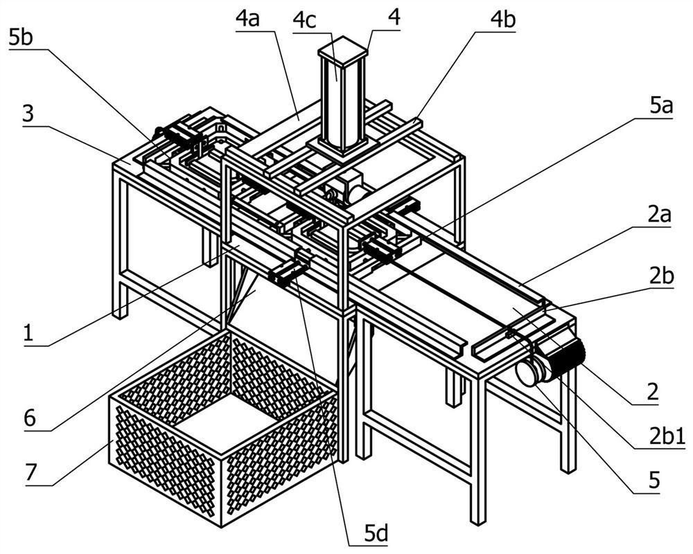
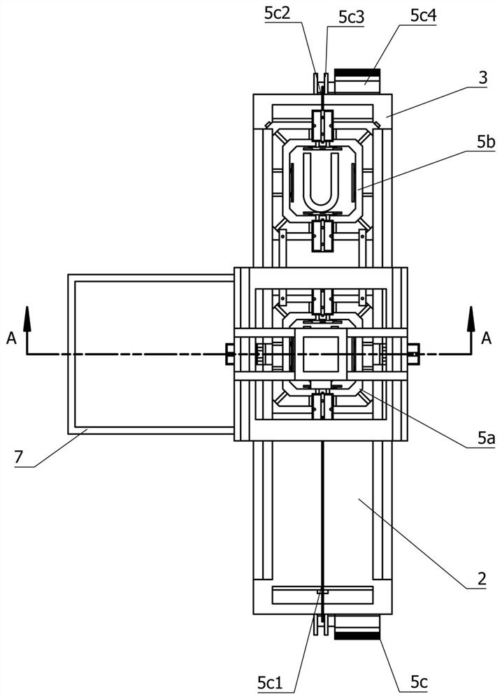
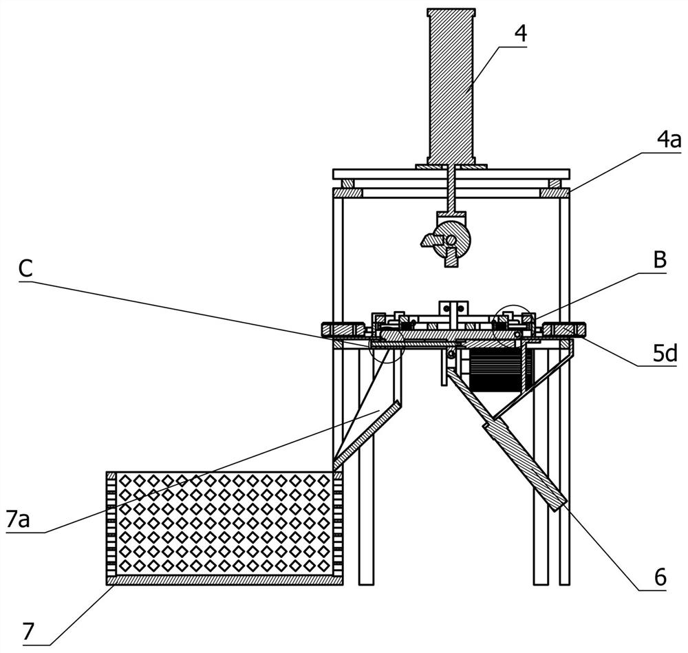
[0046] A continuous automatic stamping equipment, including a stamping table 1 and a first placement table 2 and a second placement table 3 arranged on both sides of the stamping table 1, the top of the stamping table 1 is provided with a supporting frame 4a The stamping device 4 located directly above the stamping table 1 is also provided between the first placing table 2 and the second placing table 3 to continuously place the first placing table 2 and the second placing table 3 The workpieces 1a are respectively moved to the material shifting device 5 on the stamping table 1. A discharge port is also provided on the top of the...


PUM


Abstract

The present invention relates to the field of stamping equipment, in particular to a continuous automatic stamping equipment, comprising a stamping table and a first placement table and a second placement table which are docked on both sides of the stamping table, and the top of the stamping table is provided with a Stamping device, there is also a material transfer device between the first placement table and the second placement table, a discharge port is opened on the top of the stamping table, and a discharge mechanism is also provided in the discharge port, the stamping table There is a material receiving frame docked with the discharge mechanism on the side of the side, the material shifting device includes a first accommodation mechanism and a second accommodation mechanism, and a moving mechanism is also provided on the first placement platform and the second placement platform, and A positioning mechanism is also provided on the first accommodation mechanism and the second accommodation mechanism. This application uses the synchronous movement of the first accommodation mechanism and the second accommodation mechanism, and through the first accommodation mechanism and the second The setting of the positioning mechanism on the accommodating mechanism not only improves the efficiency of workpiece processing, but also improves the qualified rate of workpiece processing.

Description

technical field [0001] The invention relates to the field of stamping equipment, in particular to a continuous automatic stamping equipment. Background technique [0002] Stamping is to rely on presses and molds to apply external force to plates, strips, pipes and profiles, etc., to cause plastic deformation or separation, so as to obtain workpieces (stamping parts) of required shape and size. Stamping and forging belong to Plastic processing (or pressure processing), collectively known as forging, stamping blanks are mainly hot-rolled and cold-rolled steel plates and steel strips, 60-70% of the world's steel products are plates, most of which are made by stamping Finished products, in traditional stamping equipment, when stamping workpieces, manual placement and manual pick-up are often used. The stamping position of the workpiece is prone to errors, the stamping efficiency is reduced, and it is easy to be accidentally injured by the stamping structure when picking up the w...

Claims


Application Information

Patent Timeline
Patent Type & Authority Patents(China)
IPC IPC(8): B21D22/06B21D43/00B21D43/14B21D43/20B21C51/00B21D37/04
CPCB21D22/06B21D43/003B21D43/145B21D43/20B21C51/00B21D37/04
Inventor 汪守丰汪东敏庞鸣朝
Owner QIJING MACHINERY
Why Eureka
Try Eureka