
Power assembly intelligent thermal management control method and system, and storage medium

A technology of intelligent thermal management and powertrain, applied in the direction of control/regulation system, non-electric variable control, lubricant temperature control, etc., can solve the problem of not being able to control engine operation according to engine working conditions, and not being able to take into account transmission cooling and Inconsistencies in heating demand and required flow changes, etc., to achieve the effects of reducing fuel consumption and emissions, reducing friction loss, and reducing the tendency of knocking

Active Publication Date: 2022-02-01
CHONGQING CHANGAN AUTOMOBILE CO LTD
View PDF12 Cites 1 Cited by
  • Summary
  • Abstract
  • Description
  • Claims
  • Application Information

AI Technical Summary

Problems solved by technology

There are several problems with this control method: first, its thermal management system can only control the cooling of the engine body, and cannot take into account the cooling and heating needs of the transmission; second, the control does not take into account the influence of vehicle speed and ambient temperature on the coolant temperature. Due to the difference in air temperature caused by wind speed and ambient temperature in the operating environment, the required flow change is inconsistent with the actual situation; third, the entire control judgment method does not consider that the temperature rises / falls beyond the threshold when the flow rate changes when the valve opening is changed. The problem of excessive jumps is caused; fourth, its thermal management system can only change the flow cross-sectional area by controlling the opening of each valve to achieve the purpose of changing the flow rate. The water pump in the system is a mechanical water pump whose speed is positively correlated with the engine speed. Therefore, it cannot be decoupled from the engine speed, and due to the limited capacity, it is impossible to control the engine to run at the optimal temperature according to the engine working conditions

Method used


Image

  • Power assembly intelligent thermal management control method and system, and storage medium
  • Power assembly intelligent thermal management control method and system, and storage medium
  • Power assembly intelligent thermal management control method and system, and storage medium

Examples


Embodiment Construction

[0027] The technical solutions implemented by the present invention will be further described below in conjunction with the accompanying drawings in the specification. The described embodiments are only part of the embodiments of the present invention. All other embodiments obtained under the labor premise all belong to the protection scope of the present invention.

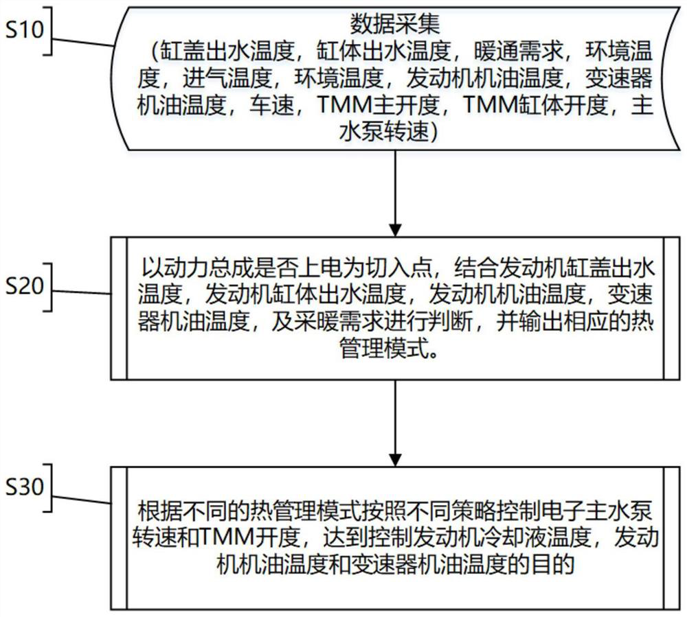
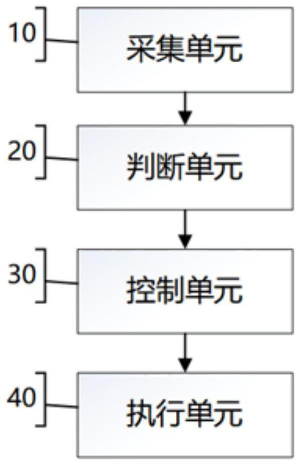
[0028] figure 1 is a flowchart of a thermal management control method according to an embodiment of the present invention. This embodiment provides a thermal management control method for an engine, such as figure 1 As shown, the thermal management method may generally include the following steps:

[0029] S10: Data collection, including cylinder head outlet water temperature, cylinder body outlet water temperature, HVAC demand, ambient temperature, intake air temperature, engine oil temperature, transmission oil temperature, vehicle speed, TMM main opening, TMM cylinder head opening and electronic Main water ...


PUM


Abstract

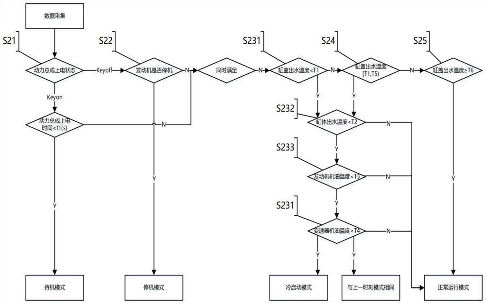
The invention discloses a power assembly intelligent thermal management control method. The method comprises the steps that: 1, a cylinder cover outlet water temperature, a cylinder body outlet water temperature, a heating and ventilation requirement, an engine oil temperature, a transmission engine oil temperature, a TMM main opening degree, a TMM cylinder cover opening degree and an electronic main water pump rotating speed are collected; 2, according to the fact that whether a power assembly is powered on or not is a cut-in point, judgment is conducted by combining the engine cylinder cover outlet water temperature, the engine cylinder body outlet water temperature, the engine oil temperature, the transmission engine oil temperature and heating requirements, and different heat management modes are output, wherein the heat management modes at least comprise a standby mode, a cold start mode, a normal operation mode and a shutdown mode; and 3, the electronic main water pump rotating speed and the TMM opening degree are controlled according to the different thermal management modes and different strategies, the flow and flow resistance of all branches of a thermal management system are adjusted, and the purpose of controlling an engine coolant temperature, the engine oil temperature and the transmission oil temperature is achieved.

Description

technical field [0001] The invention belongs to the technical field of vehicle powertrain thermal management, and in particular relates to the control technology of an intelligent thermal management system of an engine and a powertrain. Background technique [0002] With the development of electrification, thermal management systems have been upgraded from meeting reliability functional requirements to covering customer and performance requirements, thus putting forward more and higher demands on thermal management systems. For engine working conditions, the body temperature in the low-speed and small-load area should be as high as possible to reduce the heat transfer loss during the combustion process, thereby improving thermal efficiency. The body temperature in the heavy load area is as low as possible, reaching a lower level than conventional cooling systems, so as to reduce the tendency of knocking, improve thermal efficiency and reduce exhaust temperature enrichment an...

Claims


Application Information

Patent Timeline
Patent Type & Authority Applications(China)
IPC IPC(8): G05D27/02F01P5/12F01P7/14F01M5/00
CPCG05D27/02F01P5/12F01P7/14F01M5/005F01P2050/22Y02T10/12
Inventor 田溪钟睿沈惠贤刘斌吴学松
Owner CHONGQING CHANGAN AUTOMOBILE CO LTD
Learn More