
Depth camera, method for manufacturing light emitting module and terminal

A depth camera and module technology, applied in the field of ranging, can solve the problems of large volume and high overall cost, and achieve the effect of reducing volume, reducing volume and cost, and improving efficiency and accuracy

Pending Publication Date: 2022-02-01
GUANGDONG OPPO MOBILE TELECOMM CORP LTD
View PDF0 Cites 1 Cited by
  • Summary
  • Abstract
  • Description
  • Claims
  • Application Information

AI Technical Summary

Problems solved by technology

The light emission module with such a structure has good optical effects (including but not limited to efficiency, uniformity, and spot quality), but this solution is large in size and high in overall cost

Method used


Image

  • Depth camera, method for manufacturing light emitting module and terminal
  • Depth camera, method for manufacturing light emitting module and terminal
  • Depth camera, method for manufacturing light emitting module and terminal

Examples


Embodiment Construction

[0024] Embodiments of the present application will be further described below in conjunction with the accompanying drawings. The same or similar reference numerals in the drawings represent the same or similar elements or elements having the same or similar functions throughout.

[0025] In addition, the embodiments of the present application described below in conjunction with the accompanying drawings are exemplary, and are only used to explain the embodiments of the present application, and should not be construed as limiting the present application.

[0026] In the present application, unless otherwise clearly specified and limited, a first feature being "on" or "under" a second feature may mean that the first and second features are in direct contact, or that the first and second features are indirect through an intermediary. touch. Moreover, "above", "above" and "above" the first feature on the second feature may mean that the first feature is directly above or obliquel...


PUM


Abstract

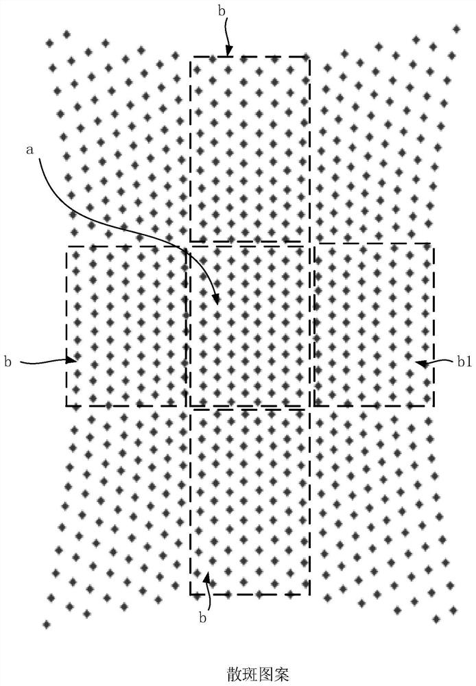
The invention discloses a depth camera, a method for manufacturing a light emitting module and a terminal. The depth camera comprises a light emitting module and a light receiving module, wherein the light emitting module comprises a light source and a diffractive optical element; the light source emits light beams to form a planar pattern; an integrated microstructure on the diffractive optical element can collimate and copy the planar pattern so as to emit a speckle pattern; a zero-level area in the speckle pattern and a plurality of first-level areas surrounding the zero-level area meet the following conditions: gapx = q[delta]x, and q is greater than 0.8 and less than 1.5; gapy is equal to p[delta]y, and p is greater than 0.8 and less than 1.5; and gapx is a first distance between the first-level area and the zero-level area in the first direction, gapy is a second distance between the first-level area and the zero-level area in the second direction, [delta]x is a first distance between two adjacent speckles arranged in the same row in the zero-level area in the first direction, and [delta]y is a second distance between two adjacent rows of speckles in the zero-level area in the second direction.

Description

technical field [0001] The present application relates to the technical field of ranging, and more specifically, to a depth camera, a method for manufacturing a light emitting module, and a terminal. Background technique [0002] The light emitting module in the depth camera generally uses a combination of "light source + lens group + diffractive optical element", in which the lens group is used to collimate the planar pattern emitted by the light source, and the diffractive optical element is used to copy and emit the copied planar pattern . The light emission module with such a structure has good optical effect (including but not limited to efficiency, uniformity and light spot quality), but this solution has a large volume and high overall cost. Contents of the invention [0003] Embodiments of the present application provide a depth camera, a method for manufacturing a light emission module, and a terminal. [0004] Embodiments of the present application provide a de...

Claims


Application Information

Patent Timeline
Patent Type & Authority Applications(China)
IPC IPC(8): G01S17/48G01S7/4911G01S7/4915
CPCG01S17/48G01S7/4911G01S7/4915
Inventor 刘海亮
Owner GUANGDONG OPPO MOBILE TELECOMM CORP LTD
Learn More