
Method for observing crack initiation and expansion of hydraulic fracture by using confocal microscope

A technology of confocal microscope and hydraulic fracture, which is used in the application of repetitive force/pulsation force to test the strength of materials, instruments, measuring devices, etc., which can solve the problem that the confocal microscope has not been popularized

Active Publication Date: 2022-01-28
TONGJI UNIV
View PDF16 Cites 0 Cited by
  • Summary
  • Abstract
  • Description
  • Claims
  • Application Information

AI Technical Summary

Problems solved by technology

[0003] However, in the field of fracture mechanics, the application of confocal microscopy has not been widely used

Method used


Image

  • Method for observing crack initiation and expansion of hydraulic fracture by using confocal microscope
  • Method for observing crack initiation and expansion of hydraulic fracture by using confocal microscope
  • Method for observing crack initiation and expansion of hydraulic fracture by using confocal microscope

Examples


preparation example Construction

[0051] In the present invention, the preparation method of the colloidal gel preferably comprises the following steps:

[0052] Mix silica gel, urea and water to obtain silica gel-urea reagent;

[0053] The urease aqueous solution is mixed with the silica gel-urea reagent to obtain the colloidal gel.

[0054] In the present invention, before mixing the urease aqueous solution and the silica gel-urea reagent, it is preferred to further include defoaming. The present invention does not specifically limit the defoaming operation, and the defoaming operation well known to those skilled in the art can be used.

[0055] In the present invention, the sample to be tested preferably further includes tracer particles. In the present invention, the average particle diameter of the tracer particles is preferably 1.0 μm; the added amount of the tracer particles is preferably 2×10 of the volume of the sample to be tested. -6 %~2×10 -7 %. In a specific embodiment of the present inventio...

Embodiment 1

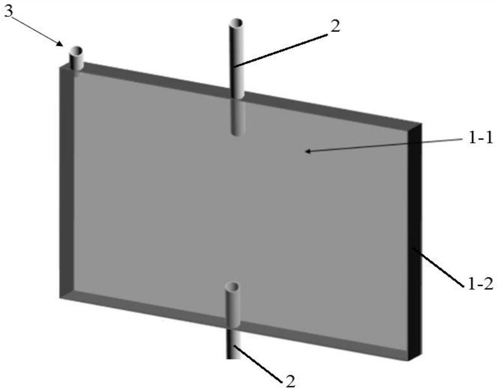
[0075] Such as figure 1 In the hydraulic fracture generating device shown, the sampling pipe 3 and the water inlet pipe 2 are both polyethylene pipes with an inner diameter of 0.034 inches and an outer diameter of 0.052 inches. The gap between the two glass sheets 1-1 is 2.0mm; the size of the two transparent glass sheets is 5cm*7.5cm*1.0mm.

[0076] To prepare colloidal gels:

[0077] The volume fraction of silicon dioxide in the colloidal gel is 7.5%, and the preparation method of the colloidal gel may further comprise the steps:

[0078] Configure 4mol / L urea solution for standby.

[0079] First add 2.5mL of urea solution with a concentration of 4mol / L to a 10mL test tube, add 3.75mL of a silica suspension with a mass fraction of 40%, add 3.75mL of distilled water, and mix well; add solidified colloid gel volume 2 ×10 -6 % of amine-modified polystyrene balls with an average particle size of about 1 μm.

[0080] Prepare another test tube, add 10 mg of urease, add 0.1 mL...


PUM

PropertyMeasurementUnit
Lengthaaaaaaaaaa
Widthaaaaaaaaaa
Thicknessaaaaaaaaaa

Abstract

The invention belongs to the technical field of fracture mechanics, and provides a method for observing crack initiation and expansion of a hydraulic fracture by using a confocal microscope. In the invention, compared with the length and the width of a sample loading cavity, the thickness of the sample loading cavity is very small, so that the surface of a hydraulic fracture is always quasi-vertical to a glass plane, namely an observation plane in a confocal microscope, and therefore, the hydraulic fracture can be observed by the confocal microscope. Through the arrangement of a hydraulic fracture generation device, the crack initiation and expansion process of a hydraulic fracture can be observed through a glass sheet of the hydraulic fracture generation device by using a confocal microscope. Compared with a traditional camera shooting record, the data obtained by the method is more coherent, and the method is more accurate for predicting the direction of a hydraulic fracture.

Description

technical field [0001] The invention relates to the technical field of fracture mechanics, in particular to a method for observing the initiation and expansion of hydraulic fractures using a confocal microscope. Background technique [0002] The full name of confocal microscope is "Laser Scanning Confocal Microscope". tool. Compared with ordinary wide-field optical microscopes, confocal microscopes have excellent characteristics such as high resolution, high sensitivity, and three-dimensional reconstruction. Nowadays, research in this field has also become a hot spot. The 2014 Nobel Prize in Chemistry was awarded to three scientists who made outstanding contributions to improving the resolution of confocal microscopes. [0003] However, in the field of fracture mechanics, the application of confocal microscopy has not been widely used. How to observe the initiation and propagation of hydraulic fractures with a confocal microscope is very important for the study of the ini...

Claims


Application Information

Patent Timeline
IPC IPC(8): G01N3/06G01N3/307G01N3/36
CPCG01N3/068G01N3/307G01N3/36G01N2203/0005G01N2203/0048G01N2203/0064G01N2203/0066G01N2203/0641G01N2203/0682
Inventor 汤继周
Owner TONGJI UNIV
Learn More