
Constant temperature assembly with furnace body

A furnace body and constant temperature technology, which is applied in the direction of furnace, furnace cooling, furnace components, etc., can solve problems such as complex copper smelting process, high temperature of the outer wall of the furnace, deformation of the furnace body, etc., to improve the heat dissipation effect, increase the contact area, and prevent unsafe The effect of regular deformation

Pending Publication Date: 2022-01-18
WEIFANG HUALONG RADIATOR
View PDF0 Cites 0 Cited by
  • Summary
  • Abstract
  • Description
  • Claims
  • Application Information

AI Technical Summary

Problems solved by technology

[0002] The copper smelting process is complicated and the process is long. The inner wall of the furnace for smelting needs high temperature resistance, so the inner wall of the furnace is generally made of refractory materials, while the outer wall of the furnace does not need the same refractory material as the inner wall of the furnace, and because the high temperature in the furnace will be transmitted to the outer wall of the furnace, resulting in The outer wall of the furnace is high temperature. If the outer wall of the furnace is always at a high temperature, the furnace body will be deformed and damaged too quickly.
[0003] In summary, there are obviously inconveniences and defects in the actual use of the existing technology, so it is necessary to improve

Method used


Image

  • Constant temperature assembly with furnace body
  • Constant temperature assembly with furnace body
  • Constant temperature assembly with furnace body

Examples


Embodiment Construction

[0020] In order to make the object, technical solution and advantages of the present invention clearer, the present invention will be further described in detail below in conjunction with the accompanying drawings. It should be understood that the specific embodiments described here are only used to explain the present invention, not to limit the present invention.

[0021] It should be noted that, in the description of the present invention, terms such as "upper", "lower", "left", "right", "inner", "outer" and other indicated directions or positional relationships are based on the terms shown in the accompanying drawings. The direction or positional relationship shown is only for convenience of description, and does not indicate or imply that the device or element must have a specific orientation, be constructed and operated in a specific orientation, and thus should not be construed as limiting the present invention.

[0022] In addition, it should be noted that, in the desc...


PUM


Abstract

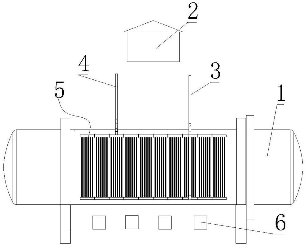
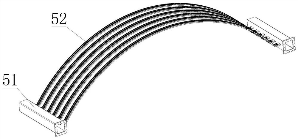
The invention is suitable for the technical field of radiators, and provides a constant temperature assembly with a furnace body. The constant temperature assembly with the furnace body comprises the furnace body, the two sides of the outer wall of the furnace body are symmetrically provided with heat dissipation assemblies in a covered mode, the upper portions of the two heat dissipation assemblies are both connected with first water pipes, the lower portions of the two heat dissipation assemblies are both connected with second water pipes, each heat dissipation assembly comprises a plurality of heat dissipation units, each heat dissipation unit comprises two water guide pipes and a plurality of heat dissipation plates fixedly connected between the two water guide pipes, each heat dissipation plate comprises an arc-shaped heat dissipation part attached to the outer wall of the furnace body and a connecting part connected with the water guide pipes, a plurality of fins are arranged on one side, away from the furnace body, of each heat dissipation part, and a plurality of first water channels with W-shaped cross sections are arranged in the heat dissipation plates. Therefore, according to the constant temperature assembly with the furnace body, the contact areas between the heat dissipation plates and water and the contact areas between the heat dissipation plates and air can be enlarged at the same time, the heat dissipation effect is improved to the maximum extent, cooling can be carried out on the outer wall of the furnace body, and deformation, damage and scrapping of the furnace body caused by overheating of the outer wall of the furnace body are prevented.

Description

technical field [0001] The invention relates to the technical field of radiators, in particular to a constant temperature assembly of a furnace body. Background technique [0002] The copper smelting process is complicated and the process is long. The inner wall of the furnace for smelting needs high temperature resistance, so the inner wall of the furnace is generally made of refractory materials, while the outer wall of the furnace does not need the same refractory material as the inner wall of the furnace, and because the high temperature in the furnace will be transmitted to the outer wall of the furnace, resulting in The outer wall of the furnace is high temperature, and the outer wall of the furnace is always in a high temperature state, which will cause the furnace body to be deformed and damaged too quickly to be scrapped. [0003] In summary, there are obviously inconveniences and defects in the actual use of the prior art, so it is necessary to improve it. Conten...

Claims


Application Information

Patent Timeline
IPC IPC(8): F27D1/12F27D9/00
CPCF27D1/12F27D9/00F27D2009/0013F27D2009/0037
Inventor 赵希民王蒙杨文鑫
Owner WEIFANG HUALONG RADIATOR
Learn More