Large-span deck type cable auxiliary beam arch combined rigid frame bridge and construction method thereof

A cable-assisted girder and long-span technology, applied in arch bridges, infrastructure engineering, bridges, etc., can solve the problems of increased axial pressure and negative bending moment at the root of the main girder, small force component of the main body of the bridge, and unfavorable construction costs. , to achieve the effect of improving bearing efficiency, overcoming cracking and deflection, and high cost performance

Pending Publication Date: 2022-01-04
林同棪国际工程咨询(中国)有限公司 +1
View PDF0 Cites 2 Cited by
  • Summary
  • Abstract
  • Description
  • Claims
  • Application Information

AI Technical Summary

Problems solved by technology

The inclination angle of the cable-stayed cables of the cable-stayed bridge with low towers is relatively small, so that the component force of the cable-stayed cables on the main body of the bridge is not large, and the vertical component force provided is limited. For a tensioned bridge, it is very small, which will increase the axial pressure and negative bending moment at the root of the main girder, resulting in the need to increase the section near the consolidation of the main girder pier and tower girder. In this case, if the span is further increased diameter, it is not conducive to saving construction costs, and the economy is poor
[0005] Due to the limitations in the mechanical properties of single structural systems such as traditional top-supported reinforced concrete arch bridges, prestressed concrete continuous rigid frame bridges, and low tower cable-stayed bridges, the prospect of developing to larger spans is limited

Method used


Image

  • Large-span deck type cable auxiliary beam arch combined rigid frame bridge and construction method thereof
  • Large-span deck type cable auxiliary beam arch combined rigid frame bridge and construction method thereof
  • Large-span deck type cable auxiliary beam arch combined rigid frame bridge and construction method thereof

Examples


Embodiment Construction

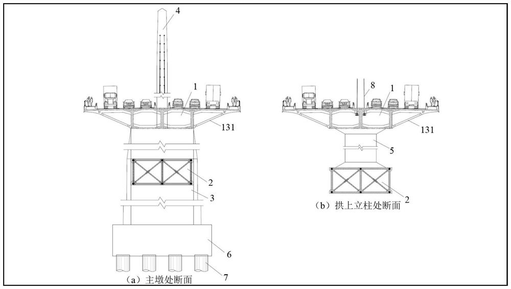
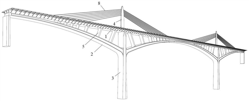
[0045] The large-span top-supported cable-assisted beam-arch composite rigid frame bridge in this embodiment includes hollow pier 3, upper chord box girder 1, lower chord box girder 2 supporting upper chord box girder 1, and hollow pier 3 and upper chord box girder 1. The upper cable tower 4 and the stay cables 8 distributed along the cable tower in the area of ​​the beam-arch joint section 13 formed by the confluence and intersection of the upper string box girder 1 and the lower string box arch 2, the upper string box girder 1, the lower string box arch 2 and the hollow pier 3 intersect to form a beam-arch triangular area, the upper string box girder 1 is supported by hollow pier 3 and arch upper column 5 in the beam-arch triangular area, and the hollow pier 3 intersects with the arch feet of the lower string box arch 2 of the side span and mid-span , the upper column 5 of the arch is evenly distributed on the vertical surface perpendicular to the lower string box arch 2; the...


PUM


Abstract

The invention discloses a large-span deck type cable auxiliary beam arch combined rigid frame bridge which comprises hollow piers, upper chord box girders, lower chord box archs for supporting the upper chord box girders, cable bent towers located over the hollow piers and the upper chord box girders, and stay cables distributed in a beam arch combination section area formed by converging and intersecting the upper chord box girders and the lower chord box arches along the cable bent towers. The upper chord box girders, the lower chord box arches and the hollow piers intersect to form a girder arch triangular area, the upper chord box girders are supported by the hollow piers and the on-arch stand columns in the girder arch triangular area, the hollow piers intersect with arch feet of the lower chord box arches of the side spans and the middle spans, and the on-arch stand columns are evenly distributed on the vertical face and perpendicular to the lower chord box arches. The bearing efficiency of a bridge structure is improved from the aspects of a structural system and a stress mechanism, the common problems of cracking and downwarping of a conventional concrete rigid frame bridge are solved, the spanning capacity of the concrete rigid frame bridge is further expanded, and the large-span deck type cable auxiliary beam arch combined rigid frame bridge has the advantages of being excellent in structural stress performance, high in cost performance, convenient to maintain and the like.

Description

technical field [0001] The invention relates to the field of bridge engineering, in particular to a large-span top-supported cable-assisted beam-arch composite rigid frame bridge which combines an upwardly supported arch, a continuous rigid frame bridge and a part of a cable-stayed bridge to give full play to the advantages of the combined structural system . Background technique [0002] The top-through reinforced concrete arch bridge is a kind of thrust bridge structure system, which has been widely used due to its advantages of low cost, beautiful shape, and large spanning capacity. Large-span upward-supported reinforced concrete arch bridges are mainly suitable for mountainous areas or mountainous urban construction environments. The huge thrust generated by them requires relatively hard and complete rocks with high compressive strength as the bearing layer of the arch foot foundation. When the geological conditions of the bridge site When it is poor, it is often imposs...

Claims


Application Information

Patent Timeline
Patent Type & Authority Applications(China)
IPC IPC(8): E01D4/00E01D2/04E01D19/02E01D19/00E01D19/16E01D11/04E01D21/00E01D21/06E01D21/10E02D27/12E02D27/14E01D101/28
CPCE01D4/00E01D2/04E01D19/02E01D19/00E01D19/16E01D11/04E01D21/00E01D21/06E01D21/10E02D27/12E02D27/14E01D2101/285
Inventor 赖亚平陈晓虎闫福成向中富刘安双乔云强李亚勇周学勇雷军谭芝文周帅
Owner 林同棪国际工程咨询(中国)有限公司
Why Eureka
Try Eureka