
Broadband stable high-gain antenna based on magnetoelectric dipole

A technology of high-gain antennas and electric dipoles, which is applied to antennas, resonant antennas, antenna supports/mounting devices, etc., can solve problems such as low gain, large gain fluctuation range, narrow bandwidth, etc., and achieve low processing cost and high gain High, improve the effect of stability

Inactive Publication Date: 2021-12-28
SOUTH CHINA UNIV OF TECH
View PDF6 Cites 0 Cited by
  • Summary
  • Abstract
  • Description
  • Claims
  • Application Information

AI Technical Summary

Problems solved by technology

The current magnetoelectric dipole antennas have common problems such as narrow bandwidth, relatively low gain, and large fluctuations in gain within the impedance bandwidth.

Method used


Image

  • Broadband stable high-gain antenna based on magnetoelectric dipole
  • Broadband stable high-gain antenna based on magnetoelectric dipole
  • Broadband stable high-gain antenna based on magnetoelectric dipole

Examples


Embodiment 1

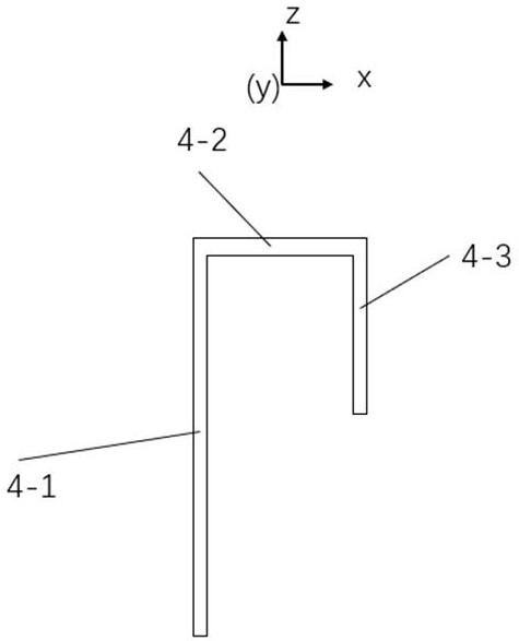
[0059] In this embodiment, the four side wall reflectors 1-2 are rectangular, the bottom reflector 1-1 is square, and are covered with a 0.035mm copper layer, and the size of the bottom reflector 1-1 is 102mm*102mm*1mm , the size of the side wall reflector 1-2 is 100mm*20mm*1mm and 102mm*20mm*1mm, the size of the through hole 6 is a circle with a radius of 1.5mm, the bottom reflector 1-1 and the four side wall reflectors The plate of 1-2 is FR4, the relative permittivity ɛ =4.4, and the dielectric loss tangent angle is tanб=0.02. The four support columns 3 are all made of cylindrical nylon columns with a height of 21mm. The size of the fixing plate 2 is 21mm*50mm*1mm, the material is FR4, and there is no copper clad layer. Placed above the fixed plate 2 is a wave-bent horizontal electric dipole 7, whose size consists of the bent length xsize of each part, the bending angle rotation_angle, and the longitudinal length l, where xsize=6.5mm, rotation_angle=50°, l=21mm, the thick...

Embodiment 2

[0062] This embodiment has carried out concrete experiment to the broadband stable high-gain antenna that embodiment 1 provides, and its experimental result is as follows Figure 4 , Figure 5 , Figure 6 , Figure 7 , Figure 8 , Figure 9 , Figure 10 , Figure 11 , Figure 12 shown.

[0063] Such as Figure 4 As shown, the broadband stable high-gain antenna provided by Embodiment 1 has three resonance points, respectively 2.2GHz, 3.2GHz, and 4.5GHz, and the reflection coefficients they have respectively are S11=-28.34dB, -24.1dB, -24.76 dB.

[0064] Such as Figure 5 As shown, the gain range of the broadband stable high-gain antenna provided by Embodiment 1 is 9.23dBi-10.96dBi, the maximum gain is 10.96dBi at this time, the frequency is 3.61GHz, and the gain at 2.45GHz is 9.33dBi.

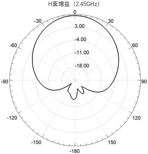
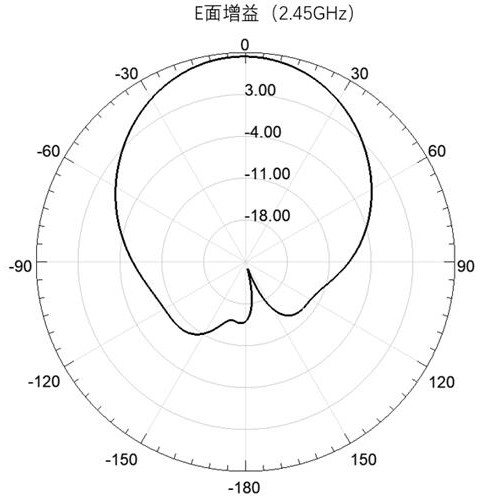
[0065] Such as Figure 6 , 7 As shown, the radiation pattern of the broadband stable high-gain antenna provided by Embodiment 1 at 2.45 GHz has good symmetry and low backward radiat...


PUM

PropertyMeasurementUnit
dielectric lossaaaaaaaaaa

Abstract

The invention discloses a broadband stable high-gain antenna based on a magnetoelectric dipole. The antenna comprises a reflection device, an inverted L-shaped feed structure, a through hole, vertical magnetic dipoles, horizontal electric dipoles and fixing plates. The inverted-L-shaped feed structure and the two fixing plates are arranged on the reflection device, the inverted-L-shaped feed structure is arranged on the upper surface of the reflection device, and the two fixing plates are arranged at the two sides of the inverted-L-shaped feed structure; the horizontal electric dipoles are arranged on the two fixing plates respectively; the two vertical magnetic dipoles are arranged at the sides, close to the inverted-L-shaped feed structure, of the two fixing plates respectively; the through hole is formed in the reflection device and is communicated with the bottom of the inverted L-shaped feed structure; an external SMA connector is connected to the inverted-L-shaped feed structure through the through hole, and the inverted-L-shaped feed structure transmits energy to the vertical magnetic dipoles and the horizontal electric dipoles through coupling feed, so that space radiation is carried out. The broadband stable high-gain antenna provided by the invention is high in radiation efficiency and high in energy utilization rate.

Description

technical field [0001] The invention relates to the technical field of antennas, in particular to a broadband stable high-gain antenna based on a magnetoelectric dipole. Background technique [0002] With the development of modern antenna technology, antennas have been widely used in mobile communications, radio and television, radar, navigation, satellites and other aspects. Antenna technology already has many characteristics of mature science, and it is still a very dynamic technical field with broad development prospects. At present, the main development directions of antennas are: multi-functional (more than one generation), intelligent (providing information processing capability), miniaturization, integration, and high performance (broadband, high gain, low sidelobe, low cross polarization, etc.). [0003] Broadband antennas have the advantages of high transmission rate, low power consumption, and the ability to improve existing spectrum utilization, which has attract...

Claims


Application Information

Patent Timeline
Patent Type & Authority Applications(China)
IPC IPC(8): H01Q9/16H01Q1/50H01Q19/10H01Q1/12H01Q1/36
CPCH01Q9/16H01Q1/50H01Q19/106H01Q1/12H01Q1/36
Inventor 唐杰周鑫马若炎罗乾峪王杏林
Owner SOUTH CHINA UNIV OF TECH
Learn More