


Quick Research
Generate reliable direction feasibility study reports for your R&D in just a few steps.

Technical Q&A
Discover and master advanced knowledge NOW. Basics, ideas, possibilities, all at once.

Find Solutions
As an expert in R&D theories, this can generate solutions to your technical problems instantly.

Evaluate Feasibility
Analyze your overall solution with one click, know your potential R&D risks in advance.

Monitor Landscape
Get weekly tech updates, stay abreast of the latest tech innovations and key insights.
Full-automatic cotton kneading device for cotton yarn production
A fully automatic, cotton yarn technology, applied in the direction of fabric kneading/softening, textile and papermaking, fabric surface trimming, etc.
- Summary
- Abstract
- Description
- Claims
- Application Information
AI Technical Summary
Problems solved by technology
Method used
Image

Examples
Embodiment 1
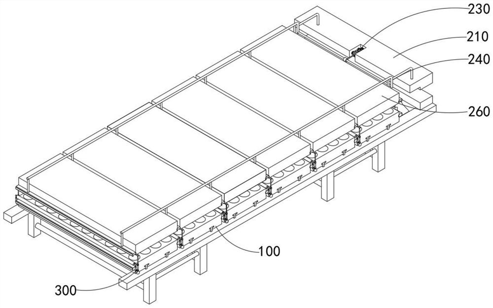
[0051] to combine Figure 4 , 6 , 7, 9, 10 and 11, a kind of fully automatic kneading device for cotton yarn production provided by the present invention comprises a supporting mechanism 100, a vibrating mechanism 200, a stabilizing mechanism 300 and a braided net 400, and the vibrating mechanism 200 is installed on the supporting mechanism 100 , the stabilizing mechanism 300 is installed outside the supporting mechanism 100 , and in addition, the braided net 400 is placed between the supporting mechanism 100 and the vibrating mechanism 200 .
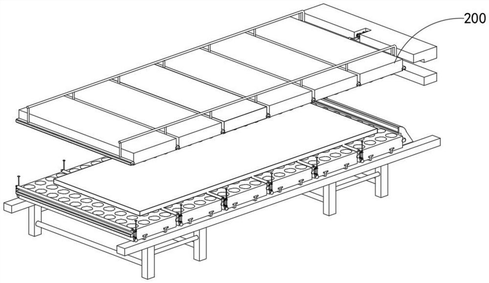
[0052] The support mechanism 100 includes a bracket 110, a limit slide 120, a material guide trough 130 and a storage plate 140, and the vibration mechanism 200 includes a fixed assembly 210, a lifting member 220, a power assembly 230, an outer frame 240, a backing plate 250 and a splicing assembly 260, And the power assembly 230 includes a servo motor 231, a rotating gear 232, an eccentric disk 233, a shaft disk 234, and a pull rod 23...
Embodiment 2
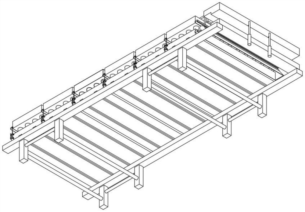
[0055] to combine Figure 9 and 10 As shown, in the above-mentioned embodiment, the material guide groove 130 used for the braided net 400 is set, and the top notch of the material guide groove 130 is used to be flat with the top surface of the storage plate 140. When the knitted net 400 passes through the inner cavity of the material guide groove 130 When moving to the top of the storage board 140, it is constrained by the guide groove 130 to the braided net 400, which can avoid the problem of wrinkles or stacking of the braided net 400, and use 142 to fix the two adjacent storage boards 140, and pass the restriction The position slide 120 is further stabilized, so that the device can be convenient for subsequent cleaning and maintenance of the operator. The support mechanism 100 also includes a bracket 110 installed at the bottom of the limit slide 120 and a material guide groove 130 installed inside the bracket 110. The board 140 includes a storage board 140 that can be pl...
Embodiment 3
[0057] to combine Figure 4 and 6 As shown, in the above-mentioned embodiment, when the small-face cotton is processed, the pressing plate 261 is pushed out along the outside of the backing plate 250, so that the device can be adapted to the rapid operation of different areas of cotton, in order to meet the needs of different equipment. Therefore, adopt and adjust the pull rod 235 and the axle disk 234 of the eccentric distance, thus can facilitate the fast operation of the operator, at the same time set a hemispherical groove on the top of the storage plate 140, and place the top of the storage plate 140 The diameter of the hemispherical groove is set to twice the diameter of the grinding block 262, so that the normal vibration of the grinding block 262 can be facilitated, and the bottom end of the L-shaped insertion rod is used to fix the top of the fixed assembly 210, so that the outer frame 240 can be integrated Can maintain a stable state with the fixed combination 210, ...
PUM
 Abstract
Description
Claims
Application Information
 - R&D Engineer
- R&D Manager
- IP Professional
- Industry Leading Data Capabilities
- Powerful AI technology
- Patent DNA Extraction
Browse by: Latest US Patents, China's latest patents, Technical Efficacy Thesaurus, Application Domain, Technology Topic, Popular Technical Reports.
© 2024 PatSnap. All rights reserved.Legal|Privacy policy|Modern Slavery Act Transparency Statement|Sitemap|About US| Contact US: help@patsnap.com