Synchronous deformation shoe capable of avoiding accidental touch

A glyph-shaped and arc-shaped technology, applied in the field of synchronously deformed shoes, can solve problems such as clumsy operation, insufficient flexibility and stability of sliding, and roller skating accidents, so as to achieve more stable transmission of screwing force, prevent accidental wheel retraction accidents, Ensure highly consistent results

Pending Publication Date: 2021-10-22
桂林新商路电子商务有限公司
View PDF0 Cites 0 Cited by
  • Summary
  • Abstract
  • Description
  • Claims
  • Application Information

AI Technical Summary

Problems solved by technology

[0002] Most of the existing roller skating deformed shoes in the market are double-row wheels, which are different from the existing roller skates in function, and the sliding is not flexible and stable enough. The structural design is complicated, and it is easy to get stuck during the deformation process. If the opening is not complete, you need to directly operate the pulley with your hands. The operation is clumsy and easy to hurt your hands. When the roller skates are in use, the relevant coordination control structure is not reasonable enough, and it is difficult to carry out multiple wheel body unfolding or retracting actions at the same time. At the same time, because the trigger position is mostly at the heel of the shoe body, the control structure is complicated and the rapid recovery during the unfolding or retracting process The stability performance is poor. At the same time, in the process of roller skating, when it comes to making actions related to the rear root touching the ground, it is easy to accidentally touch the trigger switch to cause each wheel body to make a retracting action, which will affect the performance of the roller skates and even threaten the use of them. The physical safety of those who cause roller skating accidents

Method used


Image

  • Synchronous deformation shoe capable of avoiding accidental touch
  • Synchronous deformation shoe capable of avoiding accidental touch
  • Synchronous deformation shoe capable of avoiding accidental touch

Examples


specific Embodiment approach 1

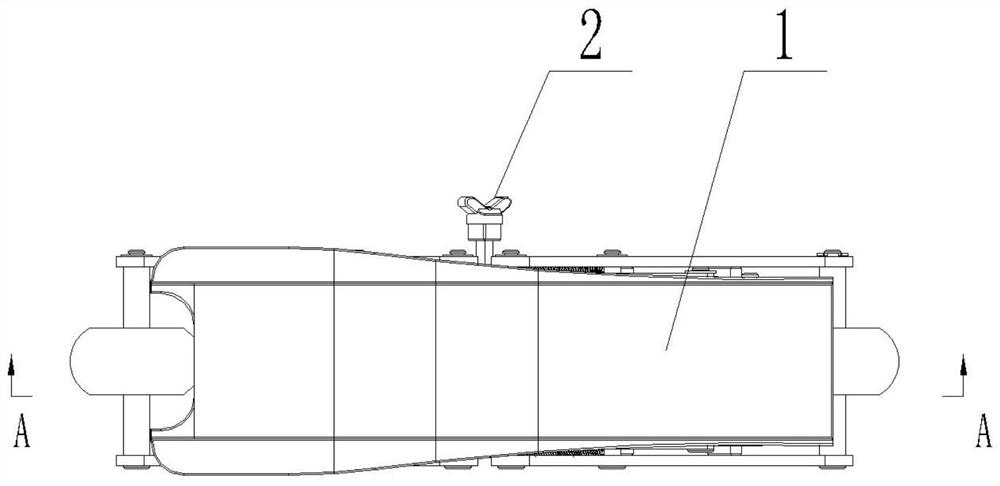
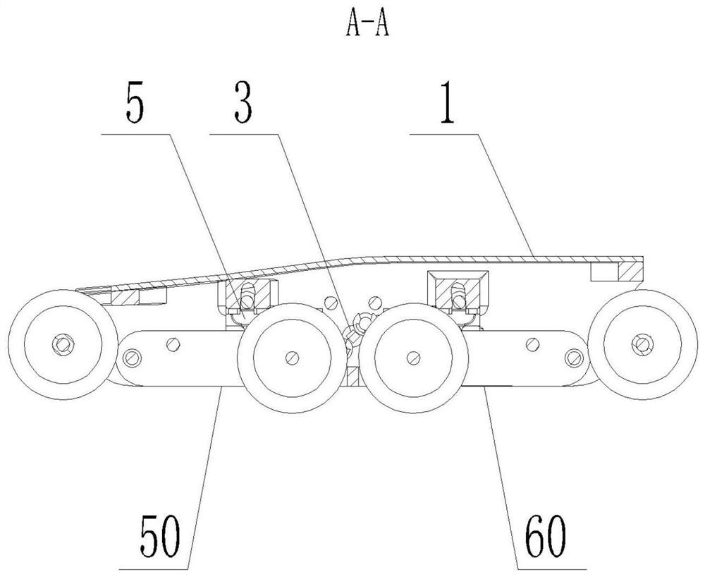
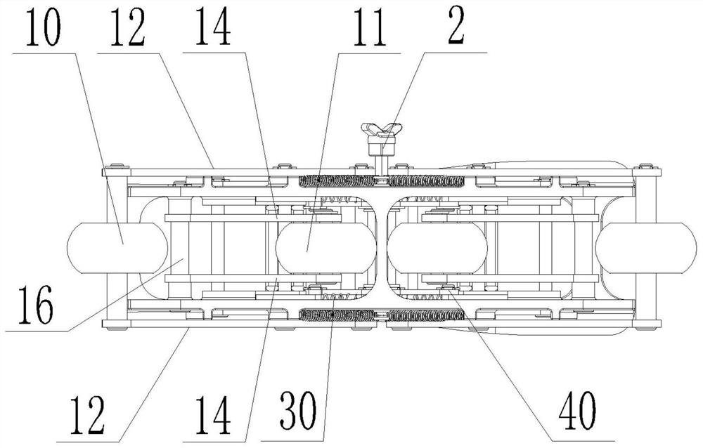
[0037] Specific implementation mode one: as figure 1 , figure 2 , image 3 , Figure 4 , Figure 5 , Image 6 , Figure 7 , Figure 8 , Figure 9 , Figure 10 , Figure 11 , Figure 12 , Figure 13 with Figure 14 As shown, the present specific embodiment adopts the following technical solutions, and the present embodiment includes the sole frame 1, the knob 2, the front control limit assembly 30, the rear control limit assembly 40, the front double-wheel support assembly 50 and the rear double-wheel Type support assembly 60, a knob 2 is arranged on the side wall of the sole frame 1, a front control limit assembly 30 and a rear control limit assembly 40 are arranged side by side in the sole frame 1, and the front control limit assembly 30 and the rear control limit assembly 40 are arranged side by side. The control limit assembly 40 is respectively hinged with the knob 2, the front double-wheel support assembly 50 and the rear double-wheel support assembly 60 are ...

specific Embodiment approach 2

[0038] Embodiment 2: This embodiment is a further limitation of Embodiment 1. A connecting rod 3 is hinged inside the sole frame 1 along its width direction. One end of the knob 2 is the force application end, and the other end of the knob 2 passes through the sole. The frame 1 side wall is connected with the connecting rod 3 behind.

specific Embodiment approach 3

[0039] Specific embodiment three: this embodiment is a further limitation of specific embodiment one or two, the rear control limit assembly 40 includes an intermediate link 4, a U-shaped connecting block 5 and a first spring 6, and the sole frame 1 The interior is processed with an inner cavity 7, and the 匚-shaped connecting block 5 is arranged in the inner cavity 7. The two sides of the sole frame 1 are respectively processed with first arc-shaped long holes 8 communicating with the inner cavity 7. The two first arc-shaped long holes A first shaft body 9 is perforated between the holes 8, one end of the intermediate connecting rod 3 is hinged to the outer wall of the connecting rod 3, the other end of the intermediate connecting rod 3 is hinged to the U-shaped connecting block 5, and the U-shaped connecting block 5 and The first spring 6 is arranged between the inner walls of the inner cavity 7, and the rear double-wheel support assembly 60 is connected with the U-shaped conn...


PUM


Abstract

The invention discloses a synchronous deformation shoe capable of avoiding accidental touch. The triggering deformation position of existing roller skate is easy to conflict with the roller skating action, so that the roller skating accident is caused by accidental touch in the roller skating process. A rotary knob is arranged on one side wall of a shoe sole frame, a front control limiting assembly and a rear control limiting assembly are arranged in the shoe sole frame side by side, the front control limiting assembly and the rear control limiting assembly are separately hinged to the rotary knob, a front double-wheel type supporting assembly and a rear double-wheel type supporting assembly are arranged at the bottom of the shoe sole frame side by side, the front control limiting assembly drives the front double-wheel type supporting assembly to be unfolded or folded through reciprocating motion in the length direction of the shoe sole frame, the rear control limiting assembly drives the rear double-wheel type supporting assembly to be unfolded or folded through reciprocating motion in the length direction of the shoe sole frame, and the front double-wheel type supporting assembly and the rear double-wheel type supporting assembly are consistent in action change state.

Description

Technical field: [0001] The invention relates to a synchronously deformed shoe that avoids accidental touch, and belongs to the technical field of sporting goods. Background technique: [0002] Most of the existing roller skating deformed shoes in the market are double-row wheels, which are different from the existing roller skates in function, and the sliding is not flexible and stable enough. The structural design is complicated, and it is easy to get stuck during the deformation process. If the opening is not complete, you need to directly operate the pulley with your hands. The operation is clumsy and easy to hurt your hands. When the roller skates are in use, the relevant coordination control structure is not reasonable enough, and it is difficult to carry out multiple wheel body unfolding or retracting actions at the same time. At the same time, because the trigger position is mostly at the heel of the shoe body, the control structure is complicated and the rapid recov...

Claims


Application Information

Patent Timeline
Patent Type & Authority Applications(China)
IPC IPC(8): A63C17/06A43B3/24A43B5/00
CPCA63C17/061A43B3/246A43B5/00
Inventor 卢伟刘尊波邱茂昌曾婉琳姚嘉吴其汉钟图壹姚远东马帅杰
Owner 桂林新商路电子商务有限公司
Why Eureka
Try Eureka