
Glass tube detector

A detector and glass tube technology, applied in the field of photoelectric detection, can solve the problems of relatively high processing requirements, the reduction of vibration isolation performance and installation accuracy by the vibration-damping barrier, to avoid force damage or functional failure, avoid direct contact, The effect of improving stability

Pending Publication Date: 2021-12-14
NAT SPACE SCI CENT CAS
View PDF1 Cites 0 Cited by
  • Summary
  • Abstract
  • Description
  • Claims
  • Application Information

AI Technical Summary

Problems solved by technology

[0003] In the existing technology, many solutions have also been proposed. For example, the patent document CN106229249A discloses a vibration damping device for installing a photomultiplier tube. The sheet compresses and fixes the inner sleeve and the vibration-damping spacer to realize the flexible connection between the inner sleeve and the outer shell, but the installation position of the inner sleeve will be changed while the compression is fixed, and the dimensional accuracy of the vibration-damping spacer is too low It will reduce the vibration isolation performance and installation accuracy. Therefore, in order to ensure the dimensional accuracy of the vibration isolation layer, the mold processing requirements are relatively high, and in this case, no vibration isolation measures were taken for the lead-out cables of the photomultiplier tube.

Method used


Image

  • Glass tube detector
  • Glass tube detector
  • Glass tube detector

Examples


Embodiment Construction

[0042] The present invention will be further described below in conjunction with specific examples.

[0043] The present invention will be further described below in conjunction with the accompanying drawings and specific embodiments.

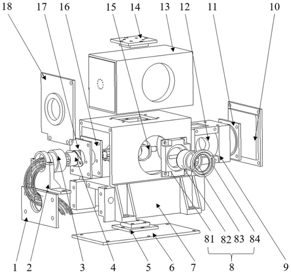
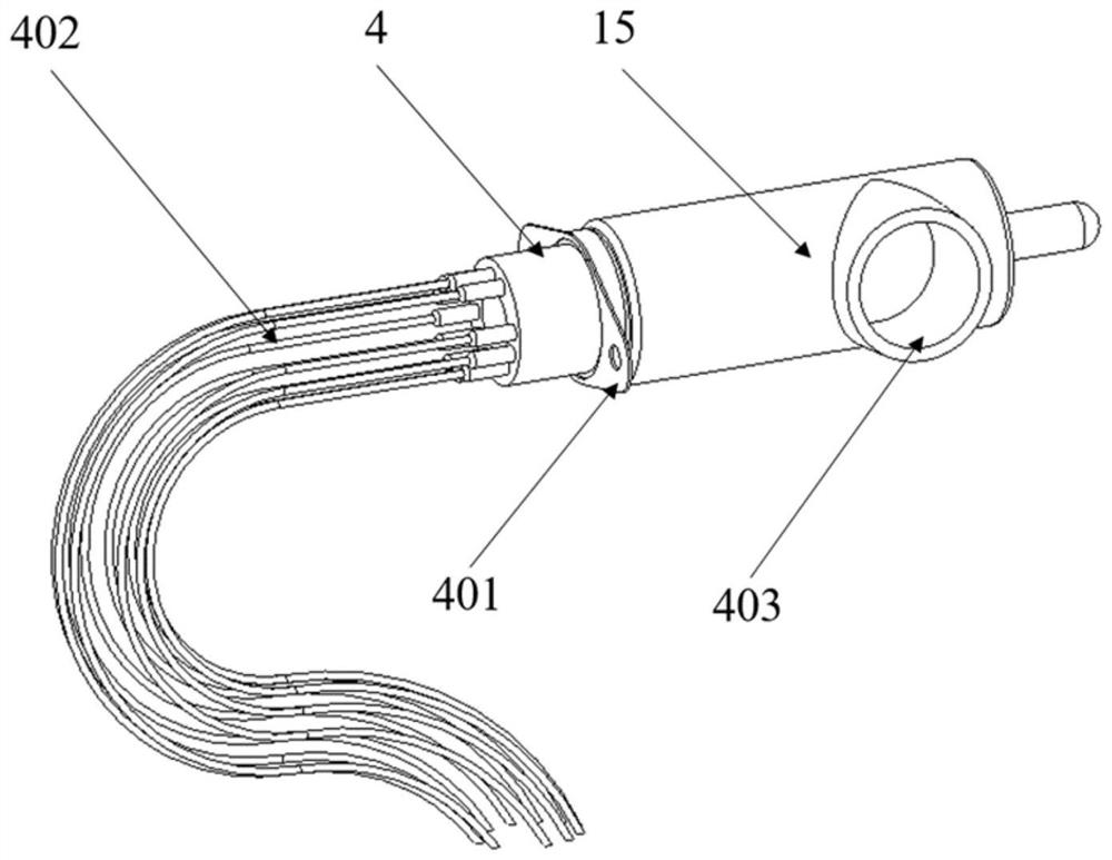
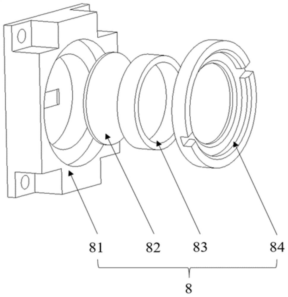
[0044] Such as figure 1 Shown, a kind of glass tube detector comprises: detector assembly (photomultiplier tube base 4 and photomultiplier tube 15), pipe sleeve assembly (pipe sleeve 9, the third pipe sleeve end cap 11, the first adhesive layer 12, The second pipe sleeve end cap 16 and the first pipe sleeve end cap 17), the diaphragm assembly 8 (diaphragm 81, optical filter 82, spacer 83, pressure ring 84), housing assembly (the first outer end cap 1, Wire clamp 2, third rubber block 3, second auxiliary top cover 5, shell 7, third outer end cover 10, second adhesive layer 13, first auxiliary top cover 14 and second outer end cover 18) and other components (PCB board 6, first auxiliary block 19, second auxiliary block 20 and limit screw 21). ...


PUM


Abstract

The invention relates to the field of photoelectric sensor detection, in particular to a glass tube detector which comprises a detection assembly, a tube sleeve assembly, a diaphragm assembly and a shell assembly. The tube sleeve assembly comprises a tube sleeve, a first tube sleeve end cover, a second tube sleeve end cover and a third tube sleeve end cover; the shell assembly comprises a shell, a first outer end cover, a second outer end cover and a third outer end cover; a first adhesive layer is filled between the detector assembly and the interior of the tube sleeve; the inner space between the shell and the tube sleeve is filled with a second glue layer; a third rubber block is fully filled at the interface of the cable on the shell; the glass tube detector further comprises a first auxiliary block, a second auxiliary block, a first auxiliary top cover and a second auxiliary top cover. The small glass tube detector is small in structural size and convenient to install, the vibration resistance and impact resistance of the detector are greatly improved while the installation precision is guaranteed, the adaptability of the small glass tube detector to the mechanical environment is enhanced, and the use scene of the detector is expanded.

Description

technical field [0001] The invention relates to the field of photoelectric detection, in particular to a glass tube detector. Background technique [0002] The glass tube detector is a weak light detector commonly used in the field of optical detection. This type of detector is usually packaged by a photocathode, a deposition material, a photoanode, an electron multiplier, insulating ceramics and a glass tube. The photocathode and the photoanode are both The grid wire structure, the above-mentioned component materials, structures and packaging processes have poor anti-vibration and impact resistance, which makes this type of detector extremely vulnerable to damage in vibration and impact environments, which limits the use of this type of detector in environments and occasions. In the field of aerospace in recent years, the demand for space-based instruments for low-light observations has continued to expand, and higher requirements have been put forward for the environmental...

Claims


Application Information

Patent Timeline
Patent Type & Authority Applications(China)
IPC IPC(8): G01J1/42G01J1/02
CPCG01J1/42G01J1/0271G01J2001/0276
Inventor 白雪松付利平贾楠付建国王天放李睿智肖思彭如意皮彦婷江芳
Owner NAT SPACE SCI CENT CAS
Learn More