Steel pipe pile structure

A technology of steel pipe piles and steel pipes, which is applied in the direction of foundation structure engineering, foundation structure repair, sheet pile walls, etc., can solve the problems of high cost, large destructiveness, and long construction period, so as to improve end bearing capacity and improve pile The effect of bearing capacity and strengthening connection

Pending Publication Date: 2021-12-10
BEIJING AEROSPACE GEOTECHN ENG INST
View PDF3 Cites 0 Cited by
  • Summary
  • Abstract
  • Description
  • Claims
  • Application Information

AI Technical Summary

Problems solved by technology

This method requires excavation of the foundation, which is destructive to the completed interior decoration, has a long construction period and high cost

Method used


Image

  • Steel pipe pile structure
  • Steel pipe pile structure
  • Steel pipe pile structure

Examples


Embodiment 1

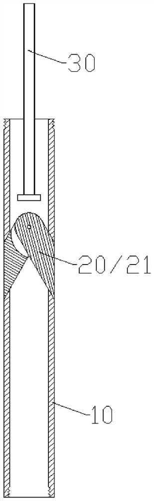
[0047] Such as Figure 1-5 As shown, a steel pipe pile structure provided in this embodiment includes: a steel pipe pile 10 and a corbel 21;

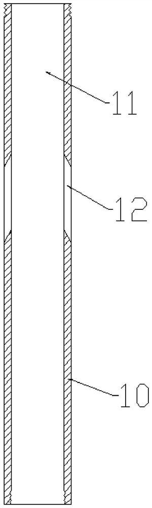
[0048] The side wall of the steel pipe pile 10 is provided with a via hole 12 connecting the inside and outside of the tube cavity 11 of the steel pipe pile 10;

[0049] The corbel 21 is inserted into the via hole 12 so as to slide out from the lumen 11 .

[0050] The present invention is simple in structure and easy to use. After the steel pipe pile 10 is laid in place, the actuator 30 is used to push the end of the corbel 21 from the tube cavity 11 of the steel pipe pile 10 to force the corbel 21 to extend out of the steel pipe from the through hole 12. pile 10, and then form the corbel 21 structure connecting the steel pipe pile 10 and the foundation, which is convenient for construction, less destructive, and low in cost.

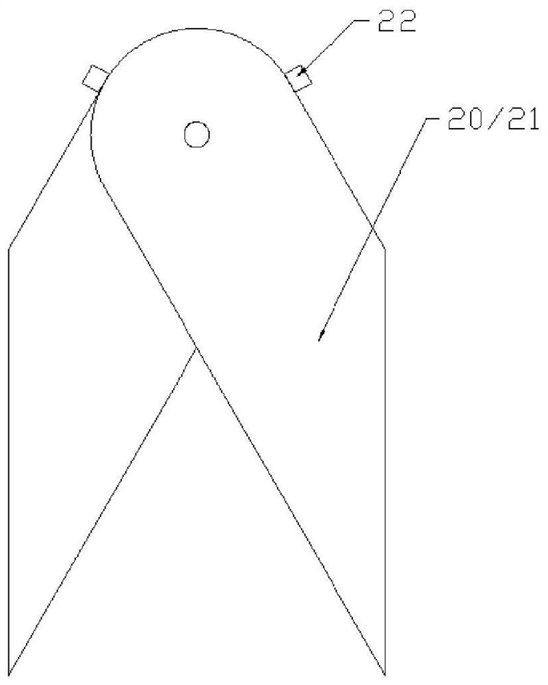
[0051] More preferably, this embodiment includes a corbel assembly 20, and the corbel assembly 20 includes mor...

Embodiment 2

[0061] The structure of this embodiment is basically the same as that of Embodiment 1, the difference is that:

[0062] In this embodiment, one or more corbel assemblies 20 are arranged at intervals in the lumen 11 of the steel pipe pile 10; when a plurality of corbel assemblies 20 are provided, as Figure 6 As shown, the adjacent corbel assemblies 20 are connected by intermediate connecting rods 52 .

[0063] A compression spring 60 is provided in the lumen 11 and at the bottom of the lowermost corbel assembly 20 , and both ends of the compression spring 60 are connected with the lowermost corbel assembly 20 and the steel pipe pile 10 After being compressed, the compression spring 60 tends to force the corbel assembly 20 to move upwards, thereby preventing the corbel 21 from extending out of the through hole 12 .

[0064] Before the steel pipe pile 10 is inserted into the set position of the foundation, the compression spring 60 can prevent the corbel assembly 20 from moving...


PUM


Abstract

The invention provides a steel pipe pile structure. The steel pipe pile structure comprises a steel pipe pile and a bracket, wherein a through hole for communicating the inside and outside of a pipe cavity of the steel pipe pile is formed in the side wall of the steel pipe pile; and the bracket can extend out of the pipe cavity in a sliding manner and is inserted into the through hole. The steel pipe pile structure provided by the invention is simple in structure and convenient to use; after the steel pipe pile is arranged in place, the tail end of the bracket is pushed from the interior of the pipe cavity of the steel pipe pile through an execution piece, the bracket is forced to stretch out of the steel pipe pile from the through hole, then a bracket structure for connecting the steel pipe pile and the foundation is formed, construction is convenient, damage is small, and cost is low.

Description

technical field [0001] The invention relates to the technical field of construction, in particular to a steel pipe pile structure. Background technique [0002] At present, in the existing reinforcement and reconstruction construction projects, due to the weak foundation or increased load, the original foundation cannot meet the requirements, and the foundation needs to be reinforced. [0003] Especially in narrow space operations, it is very common to use pile support. The traditional method is to excavate the foundation, and then build a static pressure pile foundation on the foundation or outside. After the pile is completed, add corbels or increase anchorage reinforcement on the foundation to connect. This method needs to excavate the foundation, which is destructive to the completed interior decoration, has a long construction period and high cost. Contents of the invention [0004] The object of the present invention is to provide a steel pipe pile structure to sol...

Claims


Application Information

Patent Timeline
IPC IPC(8): E02D5/28E02D3/12E02D37/00
CPCE02D5/285E02D3/12E02D37/00
Inventor 刘广成李文娟马靖原杜涛涛王春
Owner BEIJING AEROSPACE GEOTECHN ENG INST
Why Eureka
Try Eureka