
Connecting structure and method for indirect air-cooling system

An air-cooling system and connection structure technology, which is applied to the connection of indirect air-cooling systems and the connection structure of indirect air-cooling systems, can solve problems such as increasing the manufacturing cost of indirect air-cooling systems, affecting the normal operation of generator sets, and leakage of high-pressure liquid, and achieving deformation The effect of reducing the amount of bending, reducing the bending deflection, and reducing the amount of deformation

Inactive Publication Date: 2020-10-30
HUADIAN HEAVY IND CO LTD
View PDF10 Cites 1 Cited by
  • Summary
  • Abstract
  • Description
  • Claims
  • Application Information

AI Technical Summary

Problems solved by technology

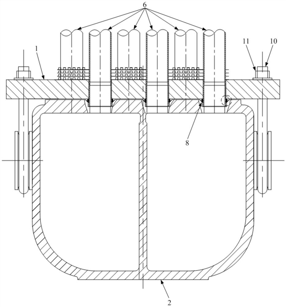
Since the lower header is filled with high-pressure liquid, in the actual working process, the tube sheet will be deformed under the action of hydraulic pressure and bolt pre-tightening force, and the deformation of the tube sheet will gradually increase from both sides to the middle, so that the tube sheet forms a similar Due to the shape of the arch bridge (that is, arched), the deformation of the tube sheet will cause a large gap between the tube sheet and the lower header, and the high-pressure liquid filled in the lower header has a great risk of leakage or even leakage, seriously affecting the normal operation of the generator set
[0003] In the prior art, in order to avoid the leakage of high-pressure liquid, the method generally adopted is to increase the thickness of the tube sheet to increase the rigidity of the tube sheet to reduce the deformation of the tube sheet, but increasing the thickness of the tube sheet will greatly increase the indirect Manufacturing cost of air cooling system

Method used


Image

  • Connecting structure and method for indirect air-cooling system
  • Connecting structure and method for indirect air-cooling system
  • Connecting structure and method for indirect air-cooling system

Examples


Embodiment Construction

[0045] The invention provides a connection structure of an indirect air cooling system, which can reduce or even avoid the increase of manufacturing cost while improving the connection and sealing effect of the tube sheet and the header to reduce the risk of liquid leakage or even leakage.

[0046] The following will clearly and completely describe the technical solutions in the embodiments of the present invention with reference to the accompanying drawings in the embodiments of the present invention. Obviously, the described embodiments are only some, not all, embodiments of the present invention. Based on the embodiments of the present invention, all other embodiments obtained by persons of ordinary skill in the art without making creative efforts belong to the protection scope of the present invention.

[0047] Such as Figure 4-Figure 19As shown, the embodiment of the present invention provides a connection structure of an indirect air cooling system, which mainly include...


PUM


Abstract

The invention discloses a connecting structure and method for an indirect air-cooling system. The connecting structure comprises a pipe plate with a pipe penetrating area, a header and a supporting piece; the header is mounted in the mode of being matched with the pipe plate, the header is connected with a first part of the pipe plate, and the first part is a part close to the edge of the long side of the pipe plate; and the supporting piece is arranged between the pipe plate and the header and can be extruded by the pipe plate and the header in a matched mode, and a second part, connected with or abutting against the pipe plate, of the supporting piece is located between the first part and the pipe penetrating area. According to the structure, by additionally arranging the supporting piece capable of serving as a deformation supporting point of the pipe plate on the position close to the connecting part of the pipe plate and the header, the deformation of the pipe plate can be reduced, compared with the mode of increasing the thickness of the pipe plate in the prior art, the improving mode of adjusting the boundary condition to reduce the bending moment of the pipe plate and reduce the deformation of the pipe plate from the mechanics principle, the adding quantity of materials used by the pipe plate can be decreased, the connecting and sealing effects of the pipe plate and theheader can be further remarkably improved, and the risk of liquid seepage or even leakage is reduced.

Description

technical field [0001] The invention relates to the technical field of generator sets, in particular to a connection structure of an indirect air cooling system, and also relates to a connection method of an indirect air cooling system suitable for the above connection structure. Background technique [0002] In the indirect air cooling system of the power plant, its core component is the indirect air cooling tube bundle. The indirect air cooling tube bundle is a tube bundle formed by making multiple base tubes pass through the tube sheet in parallel. The tube sheet is arranged on the lower header and connected with the lower header by bolts. . Since the lower header is filled with high-pressure liquid, in the actual working process, the tube sheet will be deformed under the action of hydraulic pressure and bolt pre-tightening force, and the deformation of the tube sheet will gradually increase from both sides to the middle, so that the tube sheet forms a similar Due to the...

Claims


Application Information

Patent Timeline
IPC IPC(8): F28F9/02F28F9/04
CPCF28F9/02F28F9/04
Inventor 李国栋刘学付宏伟杨晓巳
Owner HUADIAN HEAVY IND CO LTD
Learn More