
Planar transformer structure integrated with Y capacitor

A technology of planar transformers and capacitors, which is applied in the direction of variable inductors/transformers, electrical component structure associations, and parts of transformers/inductors. It can solve problems such as difficult shielding layer design, PCB wiring difficulties, and reduced Y capacitor performance. Achieve the effects of eliminating adverse effects, reducing PCB area, and improving efficiency

Active Publication Date: 2021-12-07
SOUTHEAST UNIV +1
View PDF2 Cites 0 Cited by
  • Summary
  • Abstract
  • Description
  • Claims
  • Application Information

AI Technical Summary

Problems solved by technology

The staggered arrangement of planar transformer windings can reduce the leakage inductance of the transformer and reduce the loss of the transformer, but it will bring greater interstage capacitance, which will have a negative impact on EMI, and the design of the shielding layer is also very difficult
[0004] Y capacitors can effectively reduce common-mode interference in high-frequency bands, but adding Y capacitors often requires the design of additional loops and the use of additional safety capacitors, which may cause difficulties in PCB layout
And longer PCB traces and parasitic inductance of capacitor pins, contact points, etc. will reduce the performance of Y capacitors

Method used


Image

  • Planar transformer structure integrated with Y capacitor
  • Planar transformer structure integrated with Y capacitor
  • Planar transformer structure integrated with Y capacitor

Examples


Embodiment Construction

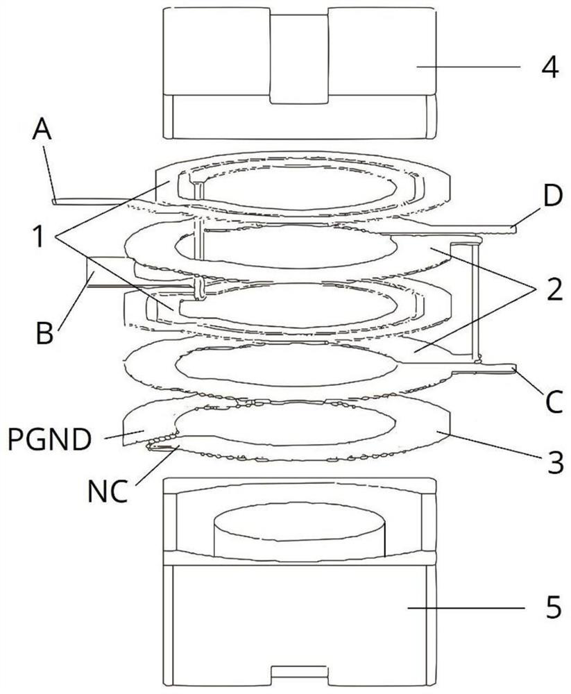
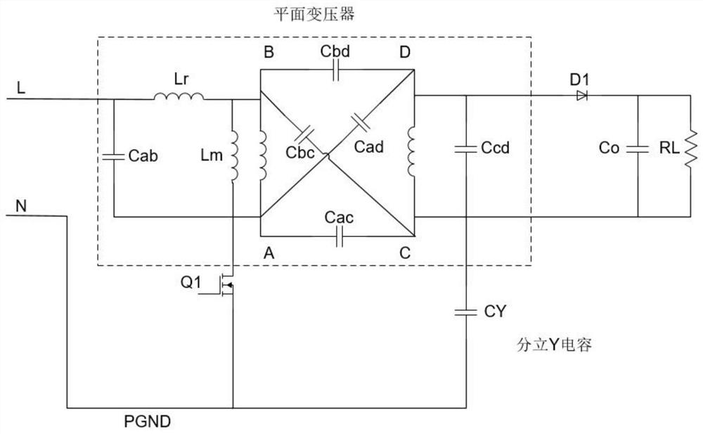
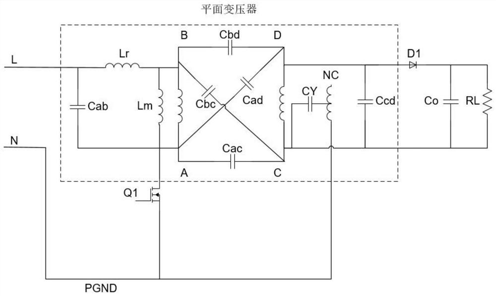
[0052] A planar transformer with integrated Y capacitors of the present invention includes a primary side winding 1, a secondary side winding 2, an auxiliary winding 3, a top magnetic core 4 and a base magnetic core 5; the primary side winding 1 is interleaved with the secondary side winding 2 arrangement; the auxiliary winding 3 is located next to the secondary winding 2, and one end of the auxiliary winding 3 is connected to the primary ground PGND to form an integrated Y capacitor CY with the secondary winding 2; the two ports of the primary winding 1 are respectively It is the first port A and the second port B, the first port A is connected to the hot spot of the primary side external circuit, and the second port B is connected to the cold point of the primary side external circuit; the two of the secondary side winding 2 The ports are respectively the third port C and the fourth port D, the third port C is connected to the cold point of the external circuit on the seconda...


PUM


Abstract

The invention discloses a planar transformer integrated with a Y capacitor, and relates to the field of electromagnetic compatibility and magnetic component design. A primary side winding and a secondary side winding are arranged in a staggered manner, and the parasitic capacitance improves the noise conduction path of the secondary side rectifier diode. One end of the auxiliary winding is connected with the primary side ground, the other end of the auxiliary winding is suspended, the auxiliary winding and the secondary side winding form an integrated Y capacitor (CY), and the noise conduction path of the primary side switch tube and the secondary side rectifier diode is improved. On the premise of keeping the advantages of low leakage inductance and high efficiency of the planar transformer with the complete cross transposition structure, the parasitic capacitance between the primary side winding and the secondary side winding is utilized to become a low-impedance path for guiding noise, the adverse effect caused by inter-stage capacitance is almost eliminated, and external conduction noise interference of the switching power supply can be effectively reduced. Meanwhile, by integrating the Y capacitor, the area of the switching power supply can be further reduced, miniaturization of the switching power supply is facilitated, and the power density of the switching power supply is improved.

Description

technical field [0001] The invention relates to the technical field of switching power supplies, in particular to electromagnetic compatibility and design of magnetic components. Background technique [0002] With the rapid development of portable electronic devices, people put forward higher and higher requirements for the improvement of the charging speed and the reduction of the volume of the charging device. Increasing the switching frequency is an effective means to reduce the size and improve the efficiency, but it will aggravate the EMI problem of the switching power supply. [0003] Compared with traditional transformers, planar transformers have significant advantages in height, volume, and quality. At the same time, it is easier to control parasitic capacitance, which can be used as a path for noise return. The thin profile of the planar transformer conductor reduces losses due to high frequency effects. At the same time, in the planar transformer structure, the ...

Claims


Application Information

Patent Timeline
Patent Type & Authority Applications(China)
IPC IPC(8): H01F27/33H01F27/36H01F27/40H01F21/00H01F27/28H01F27/34
CPCH01F27/33H01F27/36H01F27/40H01F21/00H01F27/28H01F27/346H01F2027/408Y02B70/10
Inventor 钱钦松徐诗云许胜有孙伟锋时龙兴
Owner SOUTHEAST UNIV
Learn More