Differential amplifier circuit

A differential amplifier circuit and differential pair technology, applied in the direction of differential amplifiers, amplifiers, components of amplifiers, etc., can solve the problem of reverse coupling enhancement of millimeter wave amplifiers, without offsetting gate-drain parasitic capacitance, and increasing the first amplifier tube M02 Gate charge and other issues, to achieve the effect of weakening the parasitic effect, less dependence on the process, and reducing the reverse coupling effect

Active Publication Date: 2021-03-09
CALTERAH SEMICON TECH SHANGHAI CO LTD
View PDF5 Cites 0 Cited by
  • Summary
  • Abstract
  • Description
  • Claims
  • Application Information

AI Technical Summary

Problems solved by technology

However, when the millimeter-wave amplifier works in common mode, that is, when the polarity of the first input signal and the second input signal of the millimeter-wave amplifier are the same, the neutralization capacitors Cx1 and Cx2 are connected with the first amplifying tube M01 and the second amplifying tube The polarity direction of the gate-drain parasitic capacitance of M02 is consistent, not only does not offset the gate-drain parasitic capacitance of the first amplifier tube M01 and the second amplifier tube M02, but also increases the gate charge of the first amplifier tube M02 and the second amplifier tube M02 amount, which instead leads to the enhancement of the reverse coupling phenomenon of the millimeter-wave amplifier

Method used


Image

  • Differential amplifier circuit
  • Differential amplifier circuit
  • Differential amplifier circuit

Examples


Embodiment Construction

[0027] Hereinafter, the present invention will be described in more detail with reference to the accompanying drawings. In the various figures, identical elements are indicated with similar reference numerals. For the sake of clarity, various parts in the drawings have not been drawn to scale. Also, some well-known parts may not be shown in the drawings.

[0028] In the following, many specific details of the present invention are described, such as device structures, materials, dimensions, processing techniques and techniques, for a clearer understanding of the present invention. However, the invention may be practiced without these specific details, as will be understood by those skilled in the art.

[0029] Hereinafter, it will describe in detail with reference to drawings.

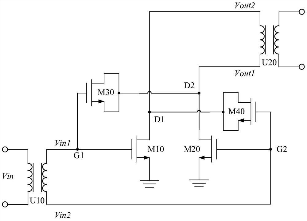
[0030] figure 2 A schematic circuit diagram showing the differential amplifier circuit of the first embodiment of the present invention.

[0031] Such as figure 2 As shown, the differential amp...


PUM


Abstract

The invention discloses a differential amplifier circuit, comprising: a first transistor and a second transistor forming a differential pair structure; a third transistor, the parasitic capacitance of the gate and drain of the third transistor is connected in parallel with the parasitic capacitance of the gate and drain of the first transistor, and the two polarities are opposite ; The gate-to-drain parasitic capacitance of the fourth transistor is connected in parallel with the gate-to-drain parasitic capacitance of the second transistor, and the polarities of the two are opposite. The present invention can neutralize the gate-drain parasitic capacitance of the differential pair tube in the differential mode and common mode mode by cross-arranging transistors, thereby reducing the reverse coupling effect, improving the stable gain of the differential amplifier, and improving the efficiency of the differential amplifier. stability. Compared with the prior art using metal stack capacitors, the differential amplifier circuit of the embodiment of the present invention is less dependent on the process, so it is easier to ensure the gate-drain parasitic capacitance between the transistor used for decoupling and the differential pair. Matching, and more conducive to the realization of mass production.

Description

technical field [0001] The present invention relates to the technical field of electronic circuits, and more specifically, to a differential amplifier circuit. Background technique [0002] The parasitic effects of complementary metal oxide semiconductor (CMOS) transistors are enhanced at high frequencies. The main reason is that the influence of the gate-drain parasitic capacitance Cgd of the MOS transistor becomes larger, and the reverse isolation performance of the transistor becomes worse. For example, in a millimeter-wave amplifier, the gate-drain parasitic capacitance of the transistor will reduce the stability and maximum gain of the millimeter-wave amplifier. Therefore, how to reduce the reverse coupling caused by the gate-drain parasitic capacitance Cgd and how to ensure the stability of the millimeter-wave amplifier It has become a core difficulty in the design process of millimeter-wave amplifiers. [0003] mmWave amplifiers typically employ a differential archit...

Claims


Application Information

Patent Timeline
Patent Type & Authority Patents(China)
IPC IPC(8): H03F1/14H03F3/45
CPCH03F3/45179
Inventor 陈嘉澍
Owner CALTERAH SEMICON TECH SHANGHAI CO LTD
Why Eureka
Try Eureka