
Cable-stayed incremental launching construction method of large-span steel beam

A technology of jacking construction and large span, applied in the direction of bridges, bridge construction, erection/assembly of bridges, etc., to achieve the effect of simple structure, saving construction cost and reducing deflection

Pending Publication Date: 2021-12-07
湖南省通盛工程有限公司 +1
View PDF11 Cites 1 Cited by
  • Summary
  • Abstract
  • Description
  • Claims
  • Application Information

AI Technical Summary

Problems solved by technology

[0003] In view of this, the purpose of the present invention is to address the deficiencies in the prior art, to provide a long-span steel girder cable-stayed jacking construction method, which solves the problem of steel beam jacking erection where temporary piers are not suitable for long-span main channels, and reduces the Reduce safety risks, improve construction efficiency, save construction costs, and effectively protect the surrounding environment, save energy and protect the environment, and have good economic, social, environmental and energy-saving benefits

Method used


Image

  • Cable-stayed incremental launching construction method of large-span steel beam
  • Cable-stayed incremental launching construction method of large-span steel beam
  • Cable-stayed incremental launching construction method of large-span steel beam

Examples


Embodiment 1

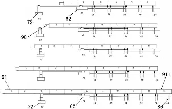
[0043] One kind of large span steel beam oblique pushing construction method, comprising the steps of:

[0044] Step 1, set the auxiliary support member, set the assembly platform, install the top push equipment;

[0045] Step 2, install the guide, pre-collating the beam;

[0046] Step 3, stepped in the top push combined mounted beam;

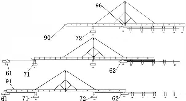
[0047] Step 4, install the cable, top push the beam body with a traverse system;

[0048] Step 5, the beam body beam, conversion system;

[0049] Step 6, dismantle cable-stayed system, push-stayed construction is completed.

[0050] Step 1 In the auxiliary support member 61 includes a front abutment, pier first column 71, the second pillar 72 and a rear abutment piers 62. Platform assembly 62 disposed at the rear end of the rear end of the abutment, the platform assembly comprising a plurality of groups temporary pier, pier chute 87 and guide rails 88 group.

[0051] Group pier chute 87 disposed between two sets of adjacent groups temporary pier, a...

Embodiment 2

[0058] This Example compared to Example 1, except that a: the step 4 of the oblique installation system comprises a pylon, tension bench 2, 3 slab anchor stent, strand 4 and 5 strut.

[0059] Beam anchoring brackets tower 1 through 3 is fixed perpendicular to the intermediate section steel beams. 4 strand tensioned symmetrically on both sides of a tower, one end of the base 2 taut strand 4 to the top tower 1, another steel beam 4 across the end of the tensioning strand by the tension of beam sets. Disposed symmetrically on both side of the strut tower 5 1 end of the support tower, and the other end sides of the intermediate section steel beams supporting steel beams.

[0060] 1 comprises a steel tower 11, the steel pipe 12 connected to the flange, the hoop 13 and stiffening bracket 14. Hoop 13 is provided on the outer periphery of the steel pipe 12 connected to the flange 11 of the steel tubes, strut tower 5 is supported by a hoop 13. Hoop 13 looped inner tube 11 is provided at th...

Embodiment 3

[0064] The present embodiment as compared with Example 2, except that a: the platform assembly comprising a set of six temporary pier, a pier group chute 87 and slide 88 in three rows. Six temporary pier group comprising a first set of temporary pier 81, a second temporary pier group 82, the third temporary pier group 83, the fourth group of temporary pier 84, the fifth and the sixth group 85 temporary pier temporary pier 86 group. Group pier chute 87 is provided between the third and the fourth group 83 temporary pier temporary pier 84 group. And the third chute 88 by temporary pier beam group 83, a second temporary pier group 82, a first set of temporary pier 81, 62 connected to the rear end of the abutment. Temporary pier top of the third group 83, the rear end of the table top bridge 62, the top of the second column piers 72, 71 is mounted on top of the first column pier walker pushing device. Beam plate girder beam spell three, six groups were provided temporary pier three lo...


PUM


Abstract

The invention discloses a cable-stayed incremental launching construction method of a large-span steel beam. The method comprises the following steps: arranging auxiliary supporting components, erecting an assembling platform, and installing incremental launching equipment; installing a guide beam, and pre-splicing a beam body; combining and splicing the beam body in a walking type incremental launching manner; installing a cable-stayed system, and performing incremental launching on the beam body provided with the cable-stayed system; enabling the beam body to fall down, and converting the system; and dismantling the cable-stayed system to complete cable-stayed incremental launching construction The large-span steel beam cable-stayed incremental launching construction method is applied to large-span beam body incremental launching with large site construction condition limitation, is simple in process, high in pertinence, small in mechanical equipment investment and convenient to operate, solves the safety and reliability problems of 80m-span three-spliced I-shaped steel plate beam construction, effectively protects the surrounding environment, saves energy, protects the environment, and has good economic, social, environment-friendly and energy-saving benefits.

Description

Technical field [0001] The present invention relates to the technical field of engineering works, particularly to a large span steel beam oblique pushing construction method. Background technique [0002] Bridge construction is widely used in highway engineering by assembling prefabricated sections, as a method of pushing bridge superstructure mounting method. Hunan Road and Bridge Construction Group Co., the construction of the bridge to Tshikapa Congo-Kinshasa Lovua segment 56Km road project start a total length of bridge 162m, arranged to span 40 + 80 + 40 continuous beam. Using the continuous beam made of steel - concrete composite beams, a reinforced concrete bridge deck, steel beam deflection is too large, super-root stress specification. And located in the main channel because the main channel should not be located temporary pier, pushing the maximum span is 80m, pushing the process too long boom. In order to increase net span bridge pushing to ensure construction safety a...

Claims


Application Information

Patent Timeline
IPC IPC(8): E01D21/00E01D21/06
CPCE01D21/00E01D21/06
Inventor 张国栋熊先勇付慧建蒋功化唐超彭官友田科桥戴湘龙刘朝华黄兴忠邓送祥祁东吴波王飞余翔刘自强王晓霞滕万山
Owner 湖南省通盛工程有限公司
Learn More