
Preparation method and application of carbon fiber/silicon carbide oriented porous skeleton

A porous skeleton and carbon fiber technology, applied in the field of phase change heat storage, can solve the problems of slow heat storage and release speed, leakage heat storage and release speed, and high technical difficulty of phase change materials, and achieve excellent thermal response speed and anti-leakage ability. The method is simple and the process cost is low

Pending Publication Date: 2021-12-07
CHINA UNIV OF MINING & TECH
View PDF4 Cites 9 Cited by
  • Summary
  • Abstract
  • Description
  • Claims
  • Application Information

AI Technical Summary

Problems solved by technology

Although heat storage by chemical reaction has a high heat storage density, its large-scale application is limited by the disadvantages of complex reaction process and equipment, high technical difficulty, and high cost.
Sensible heat storage is to store heat through the heat capacity of the sensible heat material itself, and store and release heat as the temperature rises and falls, but its heat storage density is low
Compared with sensible heat materials, latent heat materials have the advantages of high heat storage density, larger heat storage and stable heat storage and release platform when phase transition occurs, but latent heat materials are prone to leakage and heat storage and release when phase transition occurs slow speed etc.
Therefore, it is extremely important to find a filler with anti-leakage and high thermal conductivity materials. Combining it with a phase change heat storage matrix can effectively solve the problems of slow heat storage and release and leakage of phase change materials, and it can be widely used in waste heat recovery. and thermal management

Method used


Image

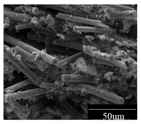
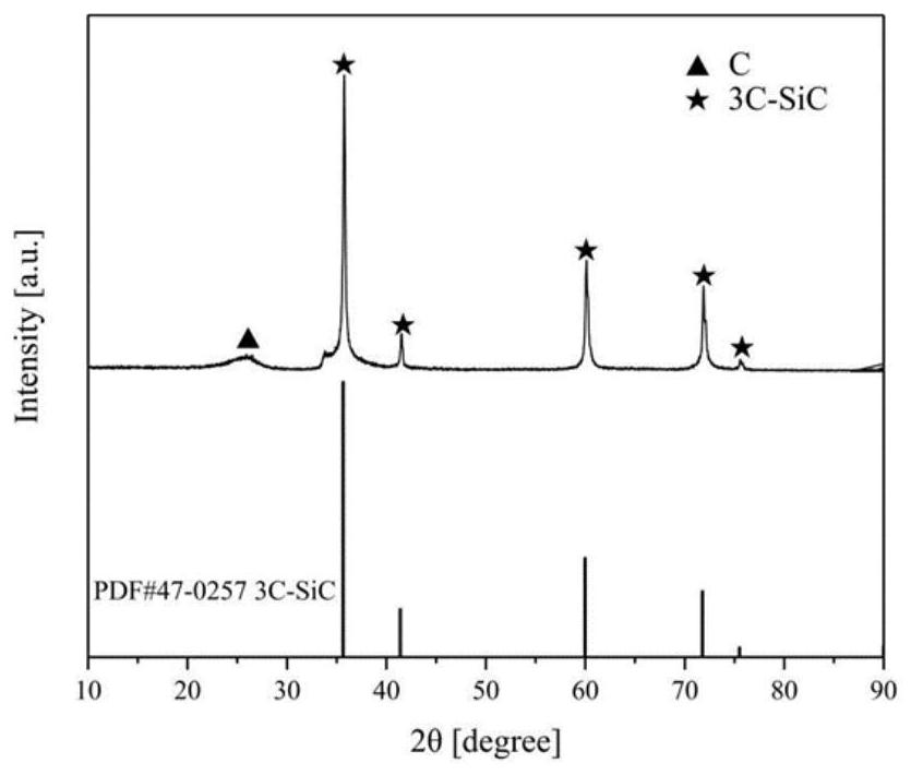
  • Preparation method and application of carbon fiber/silicon carbide oriented porous skeleton
  • Preparation method and application of carbon fiber/silicon carbide oriented porous skeleton
  • Preparation method and application of carbon fiber/silicon carbide oriented porous skeleton

Examples


Embodiment 1

[0028] 1. Preparation of carbon fiber / silicon carbide porous framework

[0029] (1) Slurry preparation: Weigh 6g of silicon dioxide powder with a particle size of 500nm and 3.085g of silicon powder (the molar ratio of silicon to silicon dioxide is 1.1), uniformly mix, dry and grind for later use. A CMC aqueous solution with a concentration of 1 wt% was prepared (0.101 g of CMC binder and 10 g of deionized water). Take 1.147g of the above-mentioned mixed powder and 0.636g of carbon fiber powder with a particle size of 13 μm, add them to the above-mentioned binder solution and stir and mix (wherein the silicon source and carbon fiber powder account for 15wt% of the slurry, and the molar ratio of carbon to silicon 2), after removing air bubbles, the slurry preparation is completed.

[0030] (2) Freezing and freeze-drying: pour the slurry into a special mold, remove air bubbles, and put the mold into a freezer at -20°C for 15 minutes for pre-freezing. Then put it in a cold trap ...

Embodiment 2

[0036] 1. Preparation of Carbon Fiber / Silicon Carbide Skeleton Structure

[0037] (1) Slurry preparation: Weigh 6g of silicon dioxide powder with a particle size of 500nm and 5.61g of silicon powder (the molar ratio of silicon to silicon dioxide is 2), uniformly mix, dry and grind for later use. Prepare a CMC solution with a concentration of 1.5wt% (the quality of the CMC binder is 0.152g, and the quality of deionized water is 10g), take 1.106g of the above-mentioned mixed powder and 0.685g of carbon fiber powder with a particle size of 13 μm, and add them to the above-mentioned adhesive Stir and mix in the binder solution (the silicon source and carbon fiber powder account for 15 wt% of the slurry, and the molar ratio of carbon to silicon is 2), and after removing air bubbles, the slurry preparation is completed.

[0038] (2) Freezing and freeze-drying: the slurry is poured into a special mold, and after removing air bubbles, the mold is placed in a -20°C freezer for pre-free...

Embodiment 3

[0043] (1) Slurry preparation: Weigh 6g of silicon dioxide powder with a particle size of 500nm and 2.806g of silicon powder (the molar ratio of silicon to silicon dioxide is 1), uniformly mix, dry and grind for later use. Prepare a CMC solution with a concentration of 0.5wt% (the quality of the CMC binder is 0.051g, and the quality of deionized water is 10g), take 1.394g of the above-mentioned mixed powder and 0.380g of carbon fiber powder with a particle size of 13 μm, and add them to the above-mentioned adhesive Stir and mix in the binder solution (the silicon source and the carbon fiber powder account for 15 wt% of the slurry, and the molar ratio of carbon to silicon is 1), and the slurry preparation is completed after removing air bubbles.

[0044] (2) Freezing and freeze-drying: pour the slurry into a special mold, remove air bubbles, and put the mold into a freezer at -20°C for 15 minutes for pre-freezing. Then the pre-frozen samples were placed in a cold trap at -65 °C...


PUM


Abstract

The invention discloses a preparation method and application of a carbon fiber / silicon carbide composite porous skeleton with a directional heat conduction characteristic, and relates to the following steps: firstly, uniformly mixing silicon and silicon dioxide powder raw materials, then uniformly dispersing the silicon source mixture and a carbon fiber raw material in a binder solution, and obtaining a three-dimensional skeleton blank with an oriented porous structure through pre-freezing, freeze forming and vacuum freeze drying treatment, wherein the forming principle is that the orientation direction of the skeleton is regulated and controlled by utilizing the effect of an oriented ice template method to prepare the three-dimensional oriented ordered porous skeleton; and finally, carrying out high-temperature calcination treatment in an inert atmosphere, and generating silicon carbide by utilizing a carbon thermal reduction reaction, so as to prepare the carbon fiber / silicon carbide composite porous skeleton with the directional heat conduction characteristic. The prepared composite porous framework body can be used as a heat conduction filler to be applied to a phase change heat storage material and a thermal interface material, the heat conductivity coefficient of a compound is improved, and the characteristic of oriented heat conduction is achieved. The method is simple in preparation process, low in cost and wide in application.

Description

technical field [0001] The invention relates to the field of phase change heat storage and thermal management of electronic equipment, in particular to a preparation method and application of a carbon fiber / silicon carbide directional porous heat-conducting skeleton. Background technique [0002] One of the main ways to achieve carbon emission reduction and carbon neutrality is to improve the utilization efficiency of fossil energy and reduce carbon emissions. The use of fossil energy is to convert heat energy into other forms of energy through combustion. Taking power plants as an example, fossil energy releases heat through combustion to convert heat energy into electrical energy as the final product. However, the amount of electricity used does not always match the amount of electricity generated, which will cause a waste of electricity. However, the storage cost of electricity is too high, so it is extremely urgent to find an economical and effective thermal energy stora...

Claims


Application Information

Patent Timeline
Patent Type & Authority Applications(China)
IPC IPC(8): C04B35/80C04B35/565C04B35/65C04B35/622C09K5/06C04B38/00
CPCC04B35/80C04B35/573C09K5/063C04B35/622C04B38/00C04B2235/3418C04B2235/422C04B2235/5248C04B2235/6022C04B2235/606C04B2235/48
Inventor 朱春宇赵呈志盛楠饶中浩
Owner CHINA UNIV OF MINING & TECH
Learn More