
Continuous production system of PET or PBT

A production system and export technology, applied in the field of polyester production system and continuous production system, can solve the problems of scraper condenser shutdown, large production loss, and hot well blockage.

Pending Publication Date: 2021-12-07
OERLIKON BARMAG HUITONG YANGZHOU ENG CO LTD
View PDF0 Cites 2 Cited by
  • Summary
  • Abstract
  • Description
  • Claims
  • Application Information

AI Technical Summary

Problems solved by technology

Finally, the oligomer particles and BDO fall into the hot well through the atmospheric leg, causing the hot well to block or damage the scraper during the scraper wall hanging process, causing the scraper condenser to stop working, and the oligomers in the hot well need to be regularly discharged into the slag discharge box for cleaning
[0007] In the actual production process, the air leg may also be blocked, causing the spray to not operate normally, causing vacuum fluctuations or loss of vacuum, and in serious cases, it has to be stopped for processing, often resulting in long processing time and huge production losses.
Traditional slag discharge boxes are mostly vertical and flat, difficult to open and clean, or square in shape, with too large sealing surface and difficult to seal; the filter screen is easily blocked, causing the filtrate to overflow directly to the discharge port with the slag discharge, resulting in The liquid discharge port is blocked; there is too much slag trapped on the top filter, and the rapid stacking will quickly cause the feed port of the slag discharge box to be blocked

Method used


Image

  • Continuous production system of PET or PBT
  • Continuous production system of PET or PBT
  • Continuous production system of PET or PBT

Examples


Embodiment Construction

[0038] In the following description of the present invention, the orientations or positional relationships indicated by the terms "front", "rear", "left", "right", "inner", "outer", etc. are based on the orientations or positional relationships shown in the drawings , is only for the convenience of describing the present invention and simplifying the description, and does not mean that the device must have a specific orientation.

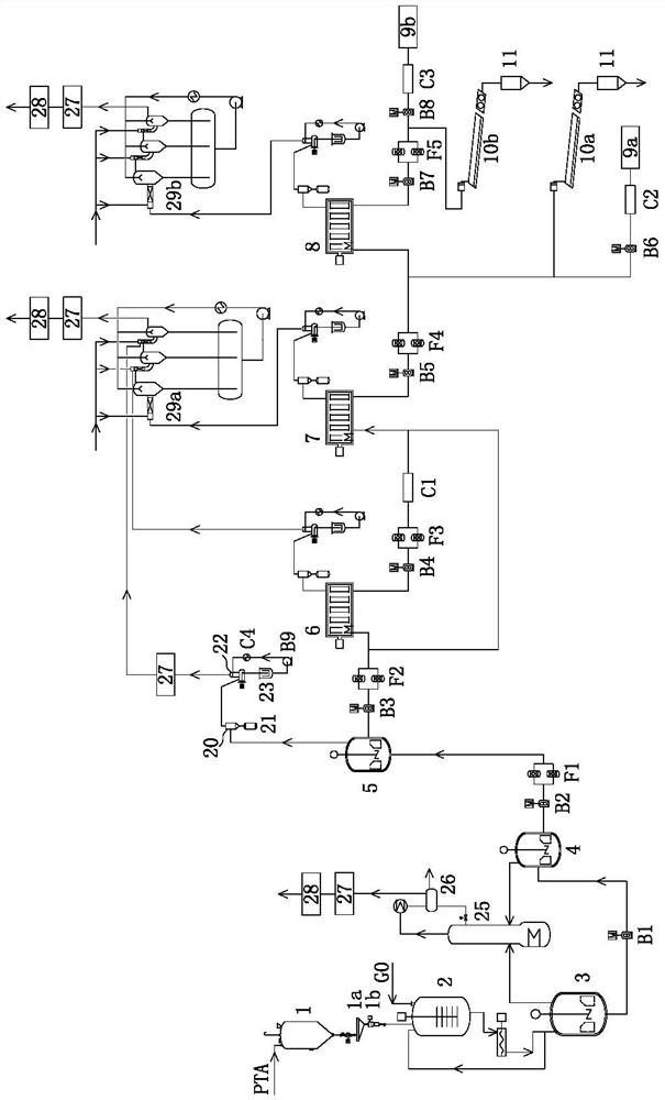
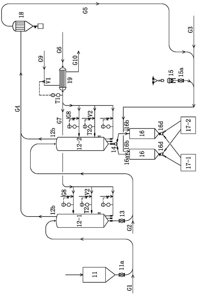
[0039] like figure 1 As shown, the continuous production system of PET or PBT of the present invention comprises PTA silo 1, and the outlet of PTA silo 1 is connected with the inlet of vibrating screen 1a by PTA discharge valve, and the outlet of vibrating screen 1a is connected with slurry by measuring scale 1b. The PTA inlet of the material preparation tank 2 is connected, and the top of the slurry preparation tank 2 is also connected with the EG or BDO feed pipe G0, and the bottom outlet of the slurry preparation tank 2 is connected to the feed p...


PUM


Abstract

The invention relates to a continuous production system of PET or PBT, a discharge port of a PTA bin is connected with a PTA inlet of a slurry preparation tank through a PTA discharge valve, a vibrating screen and a metering scale, the top of the slurry preparation tank is also connected with an EG or BDO supply pipe, and a bottom outlet of the slurry preparation tank is connected with a feed port of a first esterification kettle; a discharge port of the first esterification kettle is connected with a feed port of a second esterification kettle, a discharge port of the second esterification kettle is connected with a feed port of the first polycondensation kettle, a discharge port of the first polycondensation kettle is connected with a feed port of the second polycondensation kettle, and a discharge port of the second polycondensation kettle is connected with a feed port of a final polycondensation kettle; a discharge port of the final polycondensation reaction kettle is connected with a feed hole of a tackifying reaction kettle; the outlet of a first polycondensation material pump is also connected with the feed port of the final polycondensation reaction kettle through a surpassing pipeline; and the outlet of a melt conveying pump is connected with the inlet of the granulator 1. The system is good in compatibility, PET or PBT can be selectively produced, and diversification of PET or PBT products can be achieved.

Description

technical field [0001] The invention relates to a polyester production system, in particular to a continuous production system of PET or PBT, and belongs to the technical field of polyester chip production equipment. Background technique [0002] Polyethylene terephthalate plastics mainly include polyethylene terephthalate (PET) and polybutylene terephthalate (PBT). PET, also commonly known as polyester resin, is a condensation polymer of terephthalic acid (PTA) and ethylene glycol (EG). PBT is a polycondensate of terephthalic acid and 1,4-butanediol (BDO), and together PBT and PET are called thermoplastic polyester or saturated polyester. [0003] Bottles made of PET have the advantages of high strength, good transparency, non-toxicity, impermeability, light weight, and high production efficiency, and have been widely used. The molecular chain structure of PBT is similar to that of PET, and most of the properties are the same, except that the main chain of the molecule ha...

Claims


Application Information

Patent Timeline
Patent Type & Authority Applications(China)
IPC IPC(8): B01J19/00C08G63/78B29B9/02B29B9/16B07B1/04F26B11/16F26B21/10F26B25/04D01D1/09D01F6/62
CPCB01J19/00C08G63/785B29B9/02B29B9/16B07B1/04F26B11/16F26B21/001F26B21/10F26B25/04D01D1/09D01F6/62B01J2219/00033B07B2201/04B07B2230/01
Inventor 陶家宏钟明李立青王有超蔡青高
Owner OERLIKON BARMAG HUITONG YANGZHOU ENG CO LTD
Learn More