A kiln cleaning device for the production of special ceramic components

A technology for special ceramics and cleaning devices, applied in descaling devices, furnaces, furnace components, etc., can solve the problems of reducing the production quality of special ceramic components, affecting production efficiency, damage to special ceramic components, etc., and improving kiln production. Efficiency, reasonable and reliable structure, and the effect of ensuring cleanliness

Active Publication Date: 2021-12-31
南通博创精细陶瓷有限公司
View PDF9 Cites 0 Cited by
  • Summary
  • Abstract
  • Description
  • Claims
  • Application Information

AI Technical Summary

Problems solved by technology

[0003] In the patent document "CN202020911392.8 A rapid sintering kiln for special ceramic production", the moving mechanism installed inside the groove drives the slider to move inside the chute, and the movement of the slider facilitates the firing of ceramics. Move, so as to preheat the fired ceramics, cool after high temperature sintering, effectively improve the efficiency of ceramic sintering, drive the connecting shaft to rotate through the installed drive motor, and drive the rotation of the placing plate through the rotating of the connecting shaft, which is convenient for placing the plate The ceramics on the surface are heated evenly, so as to ensure the firing quality of the ceramics, but lack of cleaning function. With the use of the kiln, the inside of the kiln is prone to dust, etc., which is not conducive to timing cleaning after long-term use, and in order to improve the use of the kiln It needs to be cleaned regularly, which brings inconvenience to the cleaning work and affects the production efficiency, and the cleaning process is more inconvenient. It is difficult to effectively clean the dust and other foreign objects on the inner wall of the kiln and the bottom of the kiln. For precision components such as special ceramic components, etc. During production, the production quality of special ceramic components will be reduced, and even lead to damage of special ceramic components
There is still no kiln cleaning device for the production of special ceramic components with a reasonable and reliable structure, cleaning function and stable product delivery function.

Method used


Image

  • A kiln cleaning device for the production of special ceramic components
  • A kiln cleaning device for the production of special ceramic components
  • A kiln cleaning device for the production of special ceramic components

Examples


Embodiment Construction

[0033] In order to better understand the present application scheme, in connection with the drawings in the present application, the technical solutions in the present application embodiment will be clear and completely described, apparent. It is an embodiment of the present application, not all of the embodiments. Based on the embodiments in the present application, one of ordinary skill in the art will belong to all other embodiments obtained without creative labor, and should belong to the scope of the present application.

[0034] It should be noted that the specification of the present application and the claims, "first", "second", "second", or the like are used to distinguish a similar object without having to describe a particular order or ahead order. It should be understood that the data such as use can be interchanged in appropriate, so that the embodiments of the present application described herein will be described. Moreover, the terms "including" and "have" and any v...


PUM


Abstract

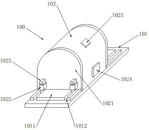
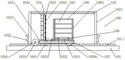
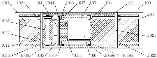
This application belongs to the technical field of kiln application, and discloses a kiln cleaning device for the production of special ceramic components, which includes: workbench, ground rail, slide rail, locking teeth, kiln, end cover, guide plate, latch, control Panel, temperature monitor, support plate, scraper, gap, end, connecting plate, middle roller, side roller, drive motor, drive sprocket, drive chain, pulley, travel motor, gear, long hole, vertical plate, Connecting shafts, cleaning rollers, transmission sprockets, transmission chains, transmission motors, hoardings, shafts, cams, lifting motors, chutes, bottom plates, limit slots, legs, side plates, placement plates, poles and sliders. This application can realize the transportation of fired products while cleaning, and at the same time has the function of cleaning the bottom of the kiln to ensure the cleanliness of the inside of the kiln. Realize the limit of products placed in the board, ensure the stability of conveying, and improve the production efficiency of the kiln.

Description

Technical field [0001] The present invention relates to a component produced by special ceramic furnace cleaning means, in particular to a special ceramic production kilns Component cleaning means, belonging furnace technology applications. Background technique [0002] Refers to a furnace fired ceramic objects and sculptures or alloyed into the furnace so that the metal objects enamel surface. Generally, bricks and stones can be made, and various specifications of size can be made as needed, and combustible gases, oils or electricity can be used. Electric kiln kiln is easier to use than the combustible gas and oil temperature control, but some potter and sculptor considered that the temperature rises too fast electric kiln, using the bore of the furnace when the temperature or the pyrometer temperature measurements cone through peephole can be seen, the furnace is a refractory brick for burning facility products, pottery molding is essential facilities. Ceramic firing of years o...

Claims


Application Information

Patent Timeline
Patent Type & Authority Patents(China)
IPC IPC(8): F27D3/12F27D25/00
CPCF27D3/123F27D25/00
Inventor 姚金梅
Owner 南通博创精细陶瓷有限公司
Why Eureka
Try Eureka