Fuel-reforming device and fuel-reforming method
A technology for reforming devices and combustion devices, applied in chemical instruments and methods, fuel supply devices, combustion air/combustion-air treatment, etc., can solve problems such as output power reduction and engine volumetric efficiency reduction, and achieve improved energy efficiency, Effects of increasing fuel yield and reducing NOx emissions
- Summary
- Abstract
- Description
- Claims
- Application Information
AI Technical Summary
Problems solved by technology
Method used
Image


Examples
Embodiment 1
[0113] This embodiment shows an embodiment in which the fuel reformer 1 according to the present invention is used to generate fuel for a combustion device whose reference fuel is methane, the fuel supply rate is W0 = 1.0 kg / h, and the power generation is 1000 Wh.
[0114] The control means 10 stores 43 cm / s as the maximum combustion rate of methane, and also stores 346 cm / s as the maximum combustion rate of hydrogen, and stores 8 cm / s as the maximum combustion rate of ammonia. Based on these maximum combustion rates, the combustion rate coefficient C of the mixture calculated using equation (1) is 0.104. Substituting the combustion rate coefficient C into equation (2), and calculating the volume fraction M of hydrogen in the mixed gas, the volume fraction is 0.319. Thus, the volume fraction of ammonia is 0.681. High-concentration hydrogen produced by the reformer 5 and ammonia from the ammonia tank are supplied to the mixing tank 7, and they are mixed. Calculate the high ca...
Embodiment 2
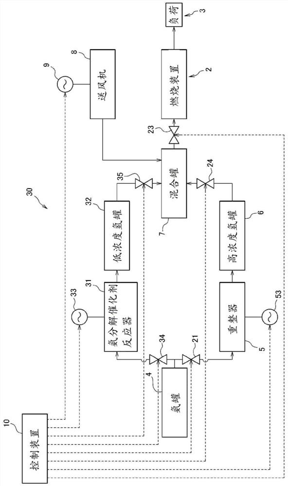
[0116] Next, an example of applying the fuel reformer 30 according to the present invention to generate fuel for a combustion device as in Embodiment 1 is shown, wherein the reference fuel is methane, and the fuel supply rate is W0=1.0kg / h, and the power generation is 1000Wh. In this embodiment, the hydrogen concentration H of the low-concentration hydrogen generated by the ammonia decomposition catalyst reactor 31 is 2L It is 7.7vol%.
[0117] The control device 10 stores the maximum combustion rate and high calorific value of methane, hydrogen, and ammonia, as in the first embodiment. Then, by using equations (1) to (6), the fuel supply rate F of the mixture gas is determined m It was 28.0 NL / h, and the mixing fraction of hydrogen was 0.319. In addition, the control device 10 converts the mixing fraction (based on volume) M of the high-concentration hydrogen tank 6 to H Determined to be 0.262. Therefore, the hydrogen supply amount from the high-concentration hydrogen t...
Embodiment 3
[0121] One embodiment of the application of the fuel reformer 30 to generate fuel for a methane gas engine is shown. The control device 10 sets the temperature of the ammonia decomposition catalyst reactor to 250° C. to generate a low-concentration hydrogen mixed gas with an ammonia decomposition rate of 10%, and stores the gas in the low-concentration hydrogen tank 32 . The composition of the generated low-concentration hydrogen mixed gas was 7.5% hydrogen, 90% ammonia, and 2.5% nitrogen. Next, the reformer 5 generates hydrogen gas with a hydrogen content of 99%, and stores this gas in the high-concentration hydrogen tank 6 . Then, 73.8% of low-concentration hydrogen and 26.2% of high-concentration hydrogen are mixed and stored in the mixing tank 7 . This blend has a maximum burn rate of 43 cm / s, matching that of methane. In addition, since the high calorific value of the mixed fuel is 61MJ / kg, which exceeds the high calorific value of methane, which is 55.5MJ / kg, the flow ...
PUM
 Abstract
Description
Claims
Application Information
 - R&D
- Intellectual Property
- Life Sciences
- Materials
- Tech Scout
- Unparalleled Data Quality
- Higher Quality Content
- 60% Fewer Hallucinations
Browse by: Latest US Patents, China's latest patents, Technical Efficacy Thesaurus, Application Domain, Technology Topic, Popular Technical Reports.
© 2025 PatSnap. All rights reserved.Legal|Privacy policy|Modern Slavery Act Transparency Statement|Sitemap|About US| Contact US: help@patsnap.com