Porous ceramic fiber diaphragm material for thermal battery and preparation method of porous ceramic fiber diaphragm material
A diaphragm material and ceramic fiber technology, which is applied in the field of porous ceramic fiber diaphragm materials for thermal batteries and its preparation, can solve the problems of low local strength, leakage of molten electrolyte, poor uniformity of ceramic diaphragm materials, etc., and achieve good discharge performance and guarantee The effect of safety performance
- Summary
- Abstract
- Description
- Claims
- Application Information
AI Technical Summary
Problems solved by technology
Method used
Image

Examples
Embodiment 1
[0045] Example 1 Porous ceramic fiber diaphragm material for thermal battery
[0046] A kind of porous ceramic fiber diaphragm material for thermal battery, wherein the quantitative of diaphragm material is 70g / m 2 , the diaphragm material method comprises the steps:
[0047] (1) According to the quantitative requirements and area of the porous ceramic fiber diaphragm material, take mullite ceramic fibers and bonding fibers (PE) with a diameter of 2-3 microns, wherein, in terms of weight percentage, ceramic fibers account for 95 %, the adhesive fiber (PE) accounts for 5%, the ceramic fiber and the adhesive fiber are mixed and put into water, and then they are decomposed in a decomposer to obtain a uniform fiber suspension.
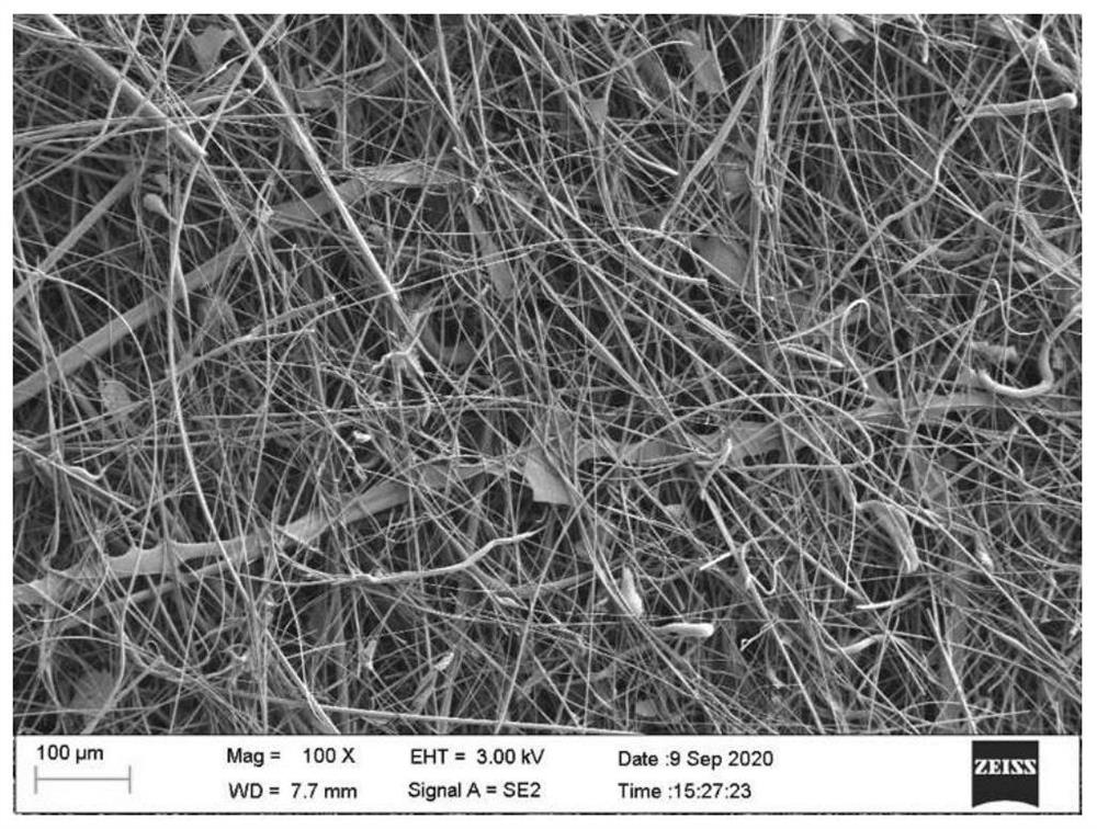
[0048] (2) The fiber suspension obtained in step (1) is wet-molded to prepare a non-woven ceramic fiber diaphragm, which is then placed in a desiccator to dry at a temperature of 95°C, and the resulting added bonding fiber The ceramic fiber, its SEM ...
Embodiment 2
[0052] Example 2 Porous ceramic fiber diaphragm material for thermal battery
[0053] A kind of porous ceramic fiber membrane material for thermal battery, wherein the quantitative of membrane material is 80g / m 2 , the diaphragm material method comprises the steps:
[0054] (1) According to the quantitative requirements and the area of the porous ceramic fiber diaphragm material, respectively weigh mullite ceramic fibers and bonding fibers (PE) with a diameter of 2-3 microns, wherein, in terms of weight percentage, mullite ceramic fibers account for 95%, bonding fiber (PE) accounts for 5%, put the ceramic fiber and bonding fiber into water after mixing, and decompose in a decomposer to obtain two uniform fiber suspensions;
[0055] (2) The non-woven ceramic fiber separator was prepared by wet forming two parts of the fiber suspension, and then placed in a desiccator for drying.
[0056] (3) Prepare the aluminum isopropoxide binder solution according to the following meth...
Embodiment 3
[0059] Example 3 Porous ceramic fiber diaphragm material for thermal battery
[0060] A kind of porous ceramic fiber membrane material for thermal battery, wherein the quantitative of membrane material is 80g / m 2 , the diaphragm material method comprises the steps:
[0061] (1) According to the quantitative requirements and area of the porous ceramic fiber diaphragm material, take mullite ceramic fibers and bonding fibers (PE) with a diameter of 5-7 microns respectively, wherein, in terms of weight percentage, mullite ceramic fibers Accounting for 95%, adhesive fiber (PE) accounted for 5%, after mixing the ceramic fiber and adhesive fiber, put it into water, and decompose in a decomposer to obtain two uniform fiber suspensions;
[0062] (2) The non-woven ceramic fiber separator was prepared by wet forming two parts of the fiber suspension, and then placed in a desiccator for drying.
[0063] (3) Prepare the aluminum isopropoxide binder solution according to the following...
PUM
| Property | Measurement | Unit |
|---|---|---|
| Diameter | aaaaa | aaaaa |
| Thickness | aaaaa | aaaaa |
| Tensile strength | aaaaa | aaaaa |
Abstract
Description
Claims
Application Information
 - R&D
- Intellectual Property
- Life Sciences
- Materials
- Tech Scout
- Unparalleled Data Quality
- Higher Quality Content
- 60% Fewer Hallucinations
Browse by: Latest US Patents, China's latest patents, Technical Efficacy Thesaurus, Application Domain, Technology Topic, Popular Technical Reports.
© 2025 PatSnap. All rights reserved.Legal|Privacy policy|Modern Slavery Act Transparency Statement|Sitemap|About US| Contact US: help@patsnap.com