
A multi-die stamping machine for hardware products

A multi-die and punching machine technology, applied in the field of punching equipment, can solve the problems of low angle iron efficiency, poor cutting quality, and reduced processing efficiency of metal steel parts, and achieve the effect of ensuring orderliness and improving processing efficiency.

Active Publication Date: 2022-01-04
启东市东浦五金有限公司
View PDF6 Cites 0 Cited by
  • Summary
  • Abstract
  • Description
  • Claims
  • Application Information

AI Technical Summary

Problems solved by technology

[0003] Chinese patent CN105170785B discloses a punching machine automatic assembly line for cutting and punching, including punching machine one, punching machine two, conveyor frame one, conveyor frame two, shearing die and punching die, punching machine one and punching machine The two are arranged side by side, the first conveyor frame is set on the left of the first punching machine, the second conveyor frame is set between the first punching machine and the second punching machine, the shearing die and the punching die are fixedly installed on the first punching machine and the second punching machine The conveyor frame 1 includes a support frame 1 and rollers, the support frame 1 is a frame structure, and at least two rollers are arranged, and the rollers are installed side by side on the top surface of the support frame 1; it solves the problem of low efficiency of the existing manual cutting and sawing machine cutting angle iron cutting Problems with poor quality and subsequent manual transport of drilling inefficiencies and labor costs
[0004] However, in this technical solution, although the problems of low drilling efficiency and low angle iron cutting efficiency are solved, it is often necessary to separate the cold drawing process and the stamping process during stamping, which leads to a reduction in the processing efficiency of hardware and steel parts

Method used


Image

  • A multi-die stamping machine for hardware products
  • A multi-die stamping machine for hardware products
  • A multi-die stamping machine for hardware products

Examples


Embodiment 1

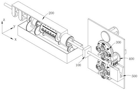
[0039] Such as figure 1 As shown, a multi-die stamping machine for hardware products, including:

[0040] Cold drawn parts 100;

[0041] A lubricating and guiding part 200, the lubricating and guiding part 200 is arranged on one side of the cold drawn part 100;

[0042] A cold drawn part 300, the cold drawn part 300 is arranged on the other side of the cold drawn part 100;

[0043] Stamping part 400, said stamping part 400 is arranged at the conveying end of said cold drawing part 300 to steel rod; And

[0044] an output part 500, the output part 500 is arranged below the stamping part 400;

[0045] The steel rods that are evenly lubricated by the lubricating and conveying part 200 to the rust surface and rust pits are guided to the cold drawn part 100 for cold drawing, and the cold drawing part 300 intermittently applies continuous increasing pressure to the steel parts drawn out of the cold drawn part 100. Subtracting the changing pushing force, the steel piece is pushed t...

Embodiment 2

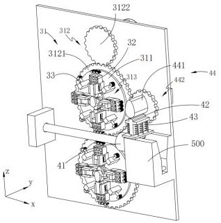
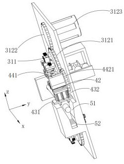
[0089] Such as figure 2 As shown, the components that are the same as or corresponding to those in the first embodiment are marked with the corresponding reference numerals in the first embodiment. For the sake of simplicity, only the differences from the first embodiment will be described below. The difference between the second embodiment and the first embodiment is that the stamping part 400 includes:

[0090] Positioning cylinder 41;

[0091] A stamping part 42, the stamping part 42 is arranged on one side of the positioning cylinder 41;

[0092] a holding part 43 on which the stamping part 42 is mounted; and

[0093] The stamping driving part 44 , the power end of the stamping driving part 44 is connected with the stamping part 42 .

[0094] In this embodiment, the stamping part 400 stamps and cuts off the steel rod delivered by the cold drawing part 300 when the push piece 32 leaves the steel rod, and the stamping part 42 on the holding part 43 is driven by the stamp...


PUM


Abstract

The invention provides a multi-die stamping machine for hardware products in the technical field of stamping equipment, comprising: a cold drawn part; Department, the cold drawing part is set on the other side of the cold drawn piece; stamping part, the stamping part is set at the delivery end of the cold drawing part to the steel rod; and the output part, the output part is set at Below the stamping part; the steel rod that is evenly lubricated by the lubrication guide part to the rust surface and the rust pit is guided to the cold drawn part for cold drawing, and the cold drawing part intermittently cold draws the steel part out of the cold drawn part The pushing force of continuous increase and decrease is applied to push the steel parts to the stamping part. The stamping part is positioned by the cold drawing part to stamp the predetermined pushing size of the steel parts. The punched parts are sorted out by the output part. The invention has the advantages that cold drawing and stamping can be carried out synchronously during stamping of the hardware steel rod, and the efficiency of cold drawing and stamping is high.

Description

technical field [0001] The invention relates to the technical field of stamping equipment, in particular to a multi-die stamping machine for hardware products. Background technique [0002] Stamping uses dies to make metal sheets into various sheet-shaped parts, shells, and container workpieces on a press, or pipe fittings into various tubular workpieces. This kind of forming process carried out in a cold state is called cold stamping, or stamping for short. [0003] Chinese patent CN105170785B discloses a punching machine automatic assembly line for cutting and punching, including punching machine one, punching machine two, conveyor frame one, conveyor frame two, shearing die and punching die, punching machine one and punching machine The two are arranged side by side, the first conveyor frame is set on the left of the first punching machine, the second conveyor frame is set between the first punching machine and the second punching machine, the shearing die and the punchi...

Claims


Application Information

Patent Timeline
Patent Type & Authority Patents(China)
IPC IPC(8): B21C37/04B21C1/20B21C9/00B21D22/02B21D37/18B21D43/00B21D43/02B08B3/08B08B5/02B08B1/04
CPCB21C37/04B21C1/20B21C9/00B21D22/02B21D37/18B21D43/006B21D43/027B08B3/08B08B5/02B08B1/165B08B1/32
Inventor 浦春伟
Owner 启东市东浦五金有限公司
Learn More