Wireless charging system and method for switching constant-current and constant-voltage charging modes

A wireless charging and charging mode technology, applied in charging/discharging current/voltage regulation, battery circuit devices, current collectors, etc., to simplify system control, improve charging efficiency, and avoid excessive current

Pending Publication Date: 2021-11-09
ELECTRIC POWER RES INST OF GUANGXI POWER GRID CO LTD
View PDF5 Cites 0 Cited by
  • Summary
  • Abstract
  • Description
  • Claims
  • Application Information

AI Technical Summary

Problems solved by technology

[0004] The purpose of the present invention is to provide a wireless charging system and method for switching constant current and constant voltage charging modes, which can solve the problems caused by a single charging mode in the prior art

Method used


Image

  • Wireless charging system and method for switching constant-current and constant-voltage charging modes
  • Wireless charging system and method for switching constant-current and constant-voltage charging modes
  • Wireless charging system and method for switching constant-current and constant-voltage charging modes

Examples


Embodiment Construction

[0028] Embodiments of the present disclosure will be described in detail below in conjunction with the accompanying drawings.

[0029] Embodiments of the present disclosure are described below through specific examples, and those skilled in the art can easily understand other advantages and effects of the present disclosure from the contents disclosed in this specification. Apparently, the described embodiments are only some of the embodiments of the present disclosure, not all of them. The present disclosure can also be implemented or applied through different specific implementation modes, and various modifications or changes can be made to the details in this specification based on different viewpoints and applications without departing from the spirit of the present disclosure. It should be noted that, in the case of no conflict, the following embodiments and features in the embodiments can be combined with each other. Based on the embodiments in the present disclosure, a...


PUM


Abstract

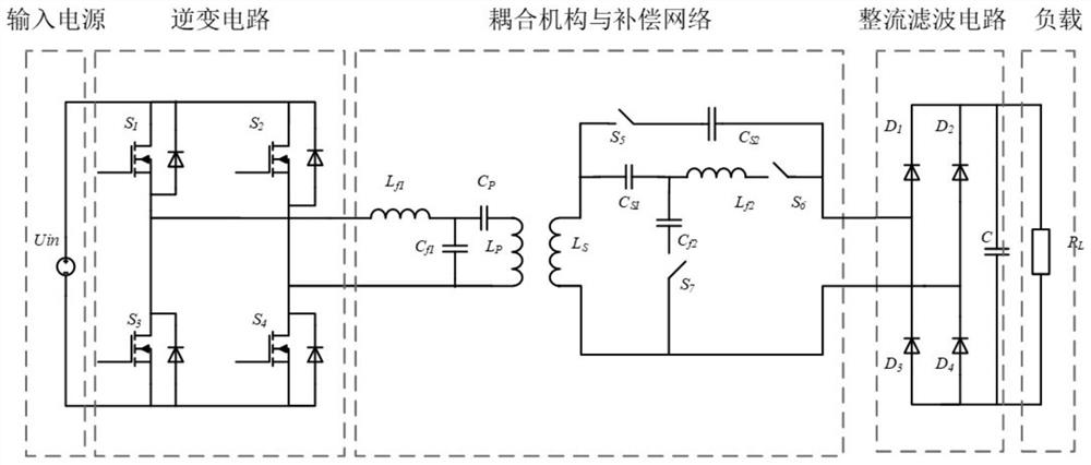
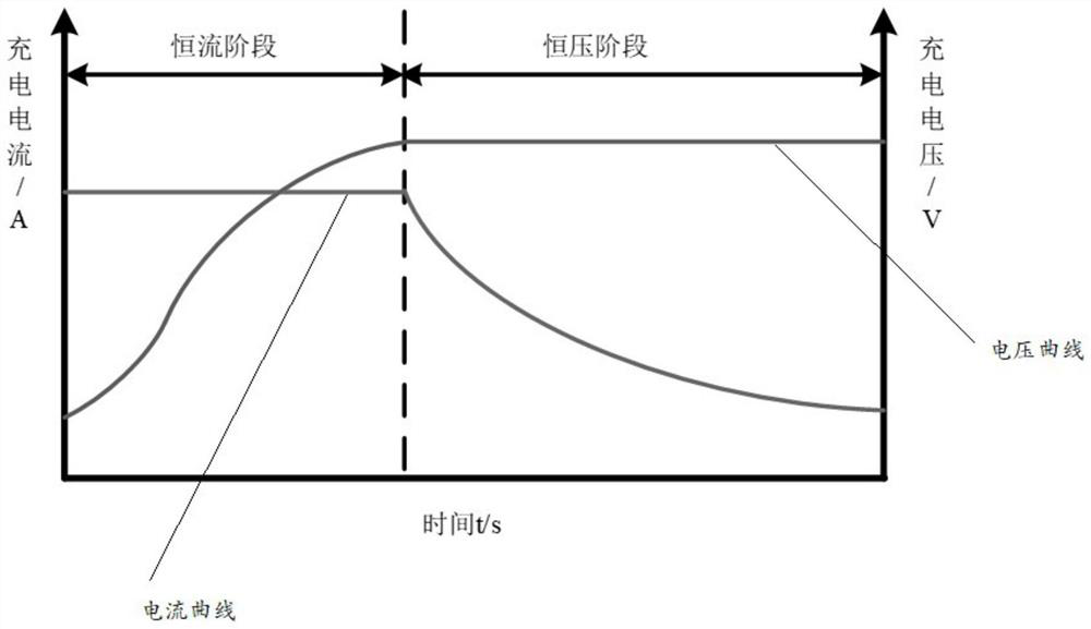
The invention provides a wireless charging system and method for switching constant-current and constant-voltage charging modes. The system comprises a transmitting end circuit and a receiving end circuit, wherein the transmitting end circuit comprises a direct-current power supply, a full-bridge inverter circuit, a primary side LCC type compensation circuit and an energy transmitting coil which are connected in sequence; the receiving end circuit comprises an energy receiving coil, a secondary side LCC type compensation circuit, a secondary side S type compensation circuit and a rectification filter circuit which are connected in sequence, wherein the secondary side LCC type compensation circuit and the secondary side S type compensation circuit are controlled to be opened and closed through a change-over switch assembly; the energy transmitting coil and the energy receiving coil are mutually coupled; in the initial charging stage, the secondary side LCC type compensation circuit is switched on, the secondary side S type compensation circuit is switched off, and constant-current charging is carried out on a load; and when the charging voltage reaches a preset voltage threshold value, the secondary side S-type compensation circuit is switched on, and the secondary side LCC-type compensation circuit is switched off, so that constant-voltage charging is carried out on the load. The constant-current charging stage and the constant-voltage charging stage not only improves the charging efficiency, but also improves the performance and the service life of the battery, and saves the cost.

Description

technical field [0001] The invention relates to the technical field of wireless energy transmission, in particular to a wireless charging system and method for switching between constant current and constant voltage charging modes. Background technique [0002] Traditional wired charging has disadvantages such as inconvenient charging and the need for manual electrical connection. With the continuous development of wireless energy transmission, the shortcomings of wired charging have been overcome. Wireless charging technology has the advantages of flexibility, reliability, and safety. The charging process does not require manual labor. Intervention is becoming more and more widely used in the fields of robots, home appliances and electric vehicles. [0003] However, wireless charging usually uses a single compensation network. This single compensation network only has the ability of constant current or constant voltage output. Constant voltage charging will cause problems ...

Claims


Application Information

Patent Timeline
Patent Type & Authority Applications(China)
IPC IPC(8): H02J7/00H02J50/10
CPCH02J7/007H02J7/00712H02J7/00304H02J50/10
Inventor 龚文兰尹立群肖静吴晓锐吴宁陈绍南韩帅陈卫东郭敏郭小璇姚知洋阮诗雅赵立夏孙乐平
Owner ELECTRIC POWER RES INST OF GUANGXI POWER GRID CO LTD
Why Eureka
Try Eureka