Outdoor embedded cable laying device

A cable laying and pre-embedding technology, which is used in cable laying equipment, transportation and packaging, and transportation of filamentous materials, etc., can solve the problems of difficult quality assurance, cable position deviation, and difficulty, and achieves a high degree of automation. Good stabilization effect, easy to handle effect

Inactive Publication Date: 2021-11-09
山西六建集团有限公司
View PDF0 Cites 0 Cited by
  • Summary
  • Abstract
  • Description
  • Claims
  • Application Information

AI Technical Summary

Problems solved by technology

[0003] With the needs of work and the actual environment, people do not complete the installation of various lines by erecting utility poles in a large area, but instead adopt a safer and more stable form. Indoor cables and wires are embedded in the wall, while outdoors It is directly buried in the ground, and the indoor cable processing is affected by the working environment, which is basically mature, but there are many problems in the outdoor cable processing: in general, there is no problem with manual processing and placement in short-distance areas, but for For some areas that are far away, it is not easy to adopt the traditional manual treatment, because the wire embedding requires opening, setting out, compaction and soil covering steps, the efficiency of manual treatment is low, and the quality is difficult to guarantee
[0004] On the other hand, using conventional machinery to place cables is prone to positional deviation, and subsequent manual adjustments are required, so that the gain outweighs the gain, the improvement in work efficiency is not obvious, and it is more troublesome to use; The cost of the automation device is high, and it is controlled by multiple motors inside. The overall device is huge, which is not conducive to stable work in a small area

Method used


Image

  • Outdoor embedded cable laying device
  • Outdoor embedded cable laying device
  • Outdoor embedded cable laying device

Examples


Embodiment Construction

[0030] The following will clearly and completely describe the technical solutions in the embodiments of the present invention with reference to the accompanying drawings in the embodiments of the present invention. Obviously, the described embodiments are only some, not all, embodiments of the present invention. Based on the embodiments of the present invention, all other embodiments obtained by persons of ordinary skill in the art without making creative efforts belong to the protection scope of the present invention.

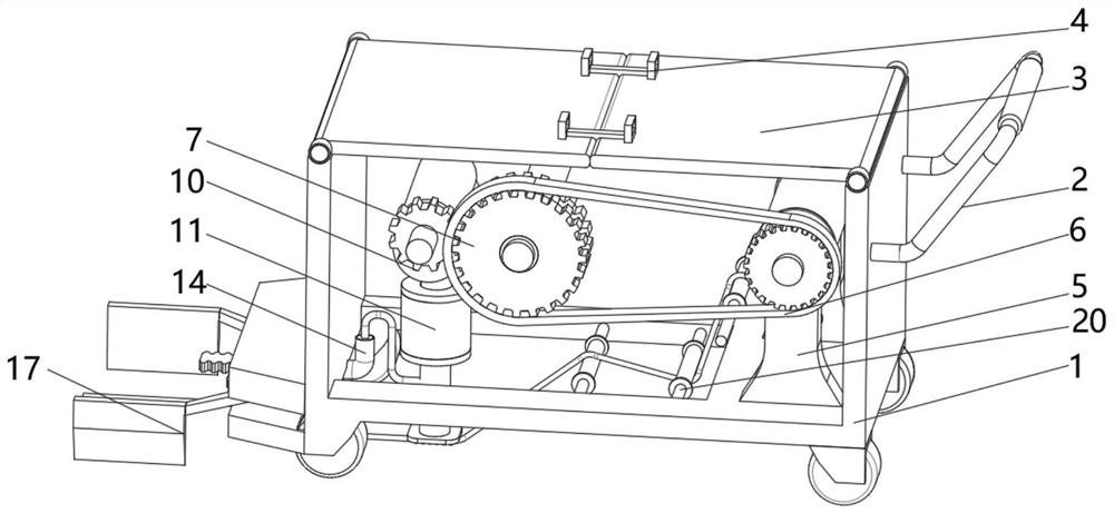
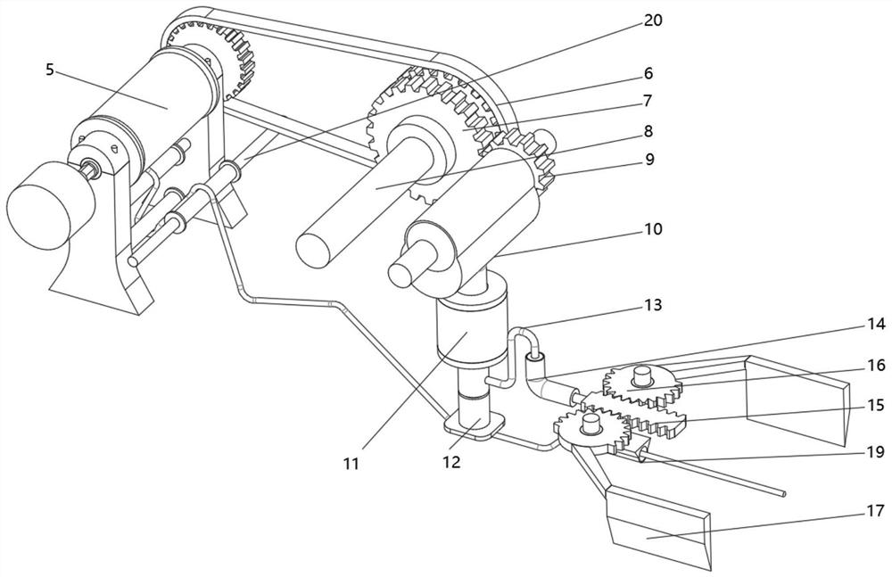
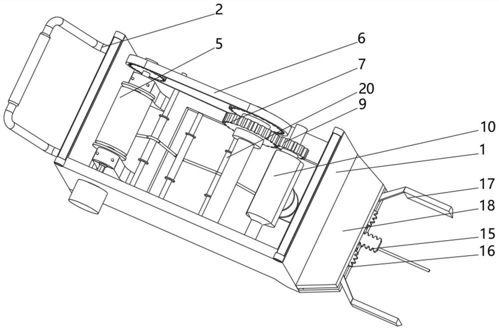
[0031] Such as Figure 1 to Figure 9 As shown, the present invention provides an outdoor pre-embedded cable laying device, including a housing 1 and an unwinding device 5, the right end of the housing 1 is fixedly installed with the unwinding device 5, and the middle part of the housing 1 is fixedly installed with a combination disc 7. The unwinding device 5 and the combination disc 7 are connected together by a chain 6. The left side of the rear end of the co...


PUM


Abstract

The invention belongs to the technical field of cable construction, and discloses an outdoor embedded cable laying device which comprises a shell and an unwinding device, wherein the unwinding device is fixedly installed at the right end of the interior of the shell, a combined disc is fixedly installed in the middle of the interior of the shell, and the unwinding device and the combined disc are connected together through a chain. The purpose of high automation degree is achieved through cooperation of the unwinding device, the lifting device, the rack and other structures. During specific use, a placement groove is formed in advance, the head end position of a cable is arranged, and then the whole trolley is manually driven to move along the groove position. In the moving process, a large-torque motor controls a cable reel to pay off slowly, and then the cable enters a pit in a limited mode after being guided by a limiting rotary drum, a pressing plate and a guiding drum.

Description

technical field [0001] The invention belongs to the technical field of cable construction, in particular to an outdoor pre-embedded cable laying device. Background technique [0002] Cable is a general term for optical cables, cables and other items. There are many uses for cables, mainly used for multiple functions such as control installation, connection equipment, and power transmission. It is a common and indispensable thing in daily life. Because cables are charged, so Installation requires special care. With the rapid development of urbanization, various high-rise buildings in many cities are quickly built. In order to ensure the effective use of office buildings, the corresponding supporting operations will be processed and laid out synchronously, among which cables are very important. One link, which is related to the electricity consumption and network conditions of the entire building, is one of the foundations for the normal operation of the entire building. [0...

Claims


Application Information

Patent Timeline
IPC IPC(8): H02G1/06B65H49/30B65H49/38B65H49/34
Inventor 胡宏青曹宗胜辛建峰乔福成王日清曲雅娟李龙刘丽昭
Owner 山西六建集团有限公司
Why Eureka
Try Eureka