
Method for adding particles in composite material and particle adding device

A composite material and mixing device technology, applied in the direction of instrumentation, design optimization/simulation, calculation, etc., can solve the problems of sucking particles, clogging, etc., to avoid particle clogging, solve the effect of oxidation slag inclusion, strong shearing effect

Active Publication Date: 2021-11-09
GUANGDONG INST OF NEW MATERIALS
View PDF11 Cites 1 Cited by
  • Summary
  • Abstract
  • Description
  • Claims
  • Application Information

AI Technical Summary

Problems solved by technology

The addition method provided by the embodiment of the present invention can make the particles enter the mixing device smoothly, which can not only reduce the contact time between the particles and the air, and solve the problem of oxidation and slag inclusion; Suction and particle clogging problems

Method used


Image

  • Method for adding particles in composite material and particle adding device
  • Method for adding particles in composite material and particle adding device
  • Method for adding particles in composite material and particle adding device

Examples


Embodiment 1

[0048] The embodiment of the present invention provides a method for adding particles in the process of mixing and preparing composite materials, including:

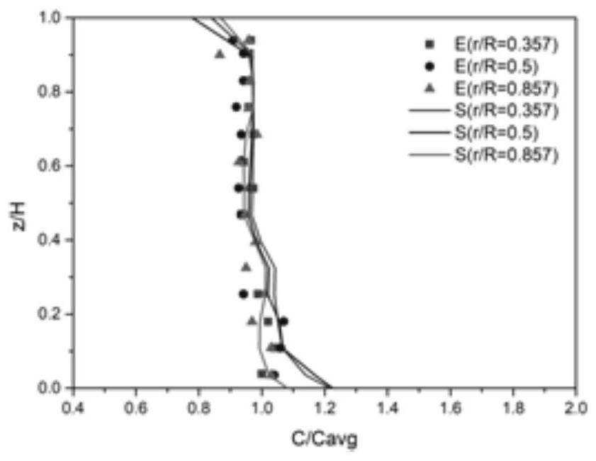
[0049] Verification: The experiment in which the turbine paddle is stirred in a stirring tank with a baffle (see the journal paper "Experimental investigation and CFD simulation of liquid–solidsolid dispersion in a stirred reactor") was selected as the comparative verification object, which is a typical For the liquid-solid-solid mixing problem, see the results figure 1 ,Right now figure 1 is the axial concentration distribution diagram of sand in the glycerin-sand-red mud liquid-solid-solid system, where, figure 1 Among them, S represents the numerical simulation, and E represents the experimental results.

[0050] according to figure 1 It can be seen that the simulation results are in good agreement with the experimental results. The accuracy of the current numerical model in simulating the liquid-solid-solid mixi...

Embodiment 2

[0053] The embodiment of the present invention provides a method for adding particles in the process of stirring and preparing composite materials, wherein the matrix material is AZ91D magnesium alloy, and its chemical composition (wt.%) is shown in the following table:

[0054] Al Zn mn Si Cu Ni Fe be Mg 9.3 0.7 0.23 0.02 0.001 0.001 0.002 0.0015 balance

[0055] The particles are Ti particles, and the experimental parameters are: the stirring speed is 400rpm, the stirring temperature is 580°C, this temperature is the semi-solid stirring temperature, the magnesium alloy melt is the continuous phase, and the primary crystal grains and Ti particles are the dispersed phase, as follows:

[0056]

[0057] The mixing device includes: a crucible, the structure of which is as Figure 4 As shown, its geometric dimensions are as follows: the opening diameter of the top of the crucible is 260mm, the diameter of the bottom is 240mm, the height...


PUM

PropertyMeasurementUnit
diameteraaaaaaaaaa
diameteraaaaaaaaaa

Abstract

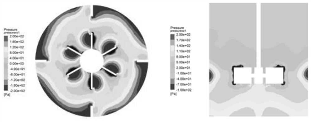
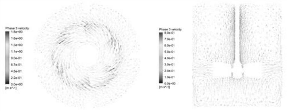
The invention relates to the technical field of composite material preparation, in particular to a method for adding particles in a composite material and a particle adding device. The method comprises the following steps: obtaining a velocity vector distribution result and a pressure field distribution result in a mixing device for mixing the base material and the particles through numerical simulation calculation; selecting an area which simultaneously meets the conditions (1) and (2) as an inlet for particles to enter the mixing device, wherein (1) refers to that the internal pressure of the mixing device is a negative value; and (2) refers to an area with a relatively high shearing speed. According to the method, the particles can smoothly enter the mixing device, the contact time of the particles and air can be shortened, and the problem of oxidation slag inclusion is solved; and the problems of suck-back and particle blockage of the mixing device at the outlet of the pipeline for transporting the particles can be effectively avoided. In addition, the particles entering the mixing device can be subjected to a strong shearing effect, and dispersion of the particles is promoted.

Description

technical field [0001] The invention relates to the technical field of composite material preparation, in particular to a particle adding method and a particle adding device in the composite material. Background technique [0002] In the prior art, adding particles to the base material can enhance the hardness, strength, wear resistance, corrosion resistance and thermal conductivity of the base material. Among them, the main preparation methods of composite materials include stirring casting method, pressure infiltration method and powder metallurgy method. Among them, stirring casting method has the advantages of simple process, equipment and low cost, and is the most likely to realize large-scale production of particle reinforcement in industry. Important method for composite materials. [0003] In the process of stirring preparation, the method of adding particles to the matrix melt is mainly divided into top adding method and bottom adding method. Add above the vortex ...

Claims


Application Information

Patent Timeline
Patent Type & Authority Applications(China)
IPC IPC(8): G06F30/23G06F30/28G06F111/10G06F113/08G06F119/14
CPCG06F30/23G06F30/28G06F2111/10G06F2113/08G06F2119/14
Inventor 尹翠翠郑开宏康跃华潘复生张志波何佳珍舒尧熊永南罗兴
Owner GUANGDONG INST OF NEW MATERIALS
Learn More