
Band-gap reference voltage source with low power consumption, low voltage and low temperature drift

A reference voltage source and low-voltage technology, which is applied in the direction of adjusting electrical variables, instruments, control/regulation systems, etc., can solve problems such as difficult to achieve effects, inability to adapt well, and difficulty in output voltage meeting low-power circuits, etc., to achieve Excellent performance and low power consumption

Active Publication Date: 2021-11-05
XIDIAN UNIV
View PDF5 Cites 2 Cited by
  • Summary
  • Abstract
  • Description
  • Claims
  • Application Information

AI Technical Summary

Problems solved by technology

[0005] The traditional structure of the bandgap reference voltage source has significant disadvantages
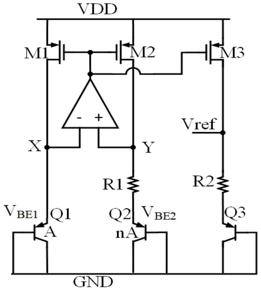
Specifically, in practical applications, due to the emitter junction voltage V of the triode BE The negative temperature coefficient is non-linear, and it is difficult to achieve good results only through first-order temperature compensation
And due to the emitter junction voltage V of transistor Q3 BE3 Larger, the output voltage is difficult to meet the needs of low-power circuits
Therefore, the traditional bandgap reference voltage source structure cannot well adapt to increasingly advanced low-voltage and low-power circuits

Method used


Image

  • Band-gap reference voltage source with low power consumption, low voltage and low temperature drift
  • Band-gap reference voltage source with low power consumption, low voltage and low temperature drift
  • Band-gap reference voltage source with low power consumption, low voltage and low temperature drift

Examples


Embodiment Construction

[0031] In order to further explain the technical means and effects of the present invention to achieve the intended purpose of the invention, a low-power, low-voltage, low-temperature drift bandgap reference voltage source proposed according to the present invention will be described in detail below in conjunction with the accompanying drawings and specific implementation methods. illustrate.

[0032] The aforementioned and other technical contents, features and effects of the present invention can be clearly presented in the following detailed description of specific implementations with accompanying drawings. Through the description of specific embodiments, the technical means and effects of the present invention to achieve the intended purpose can be understood more deeply and specifically, but the accompanying drawings are only for reference and description, and are not used to explain the technical aspects of the present invention. program is limited.

[0033]It should b...


PUM


Abstract

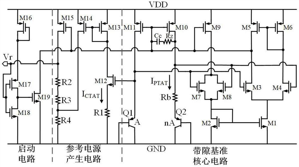
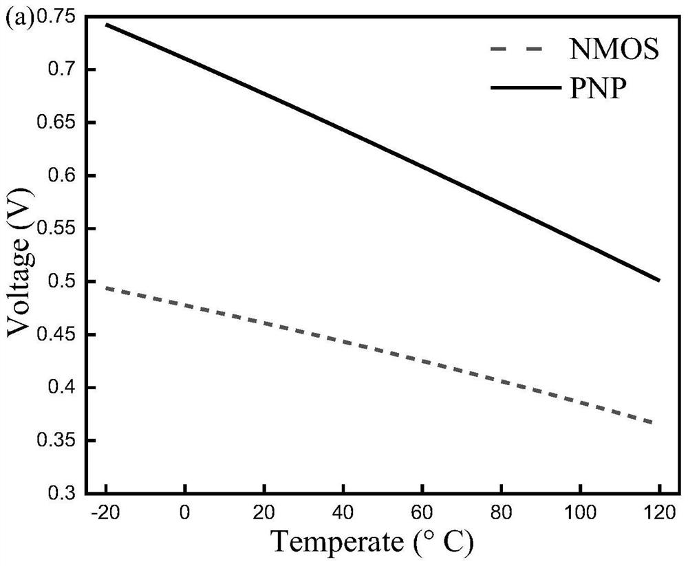
The invention discloses a band-gap reference voltage source with low power consumption, low voltage and low temperature drift, which comprises a starting circuit, a band-gap reference core circuit and a reference power supply generation circuit, wherein the starting circuit is used for starting the band-gap reference core circuit and the reference power supply generation circuit in a power supply voltage electrifying process; the band-gap reference core circuit is used for generating positive temperature coefficient current; the reference power supply generation circuit is used for generating a negative temperature coefficient current, performing preliminary compensation on the negative temperature coefficient current by using a source negative feedback structure composed of a triode and an NMOS transistor, performing mutual compensation on voltages generated by the positive temperature coefficient current and the negative temperature coefficient current by using resistor connection, and obtaining a reference voltage source. According to the band-gap reference voltage source, the reference voltage source with a low temperature drift coefficient can be obtained by subtracting the negative temperature coefficient of the emitter junction voltage of the triode and the negative temperature coefficient of the gate source voltage of the NMOS transistor and source negative feedback.

Description

technical field [0001] The invention belongs to the technical field of integrated circuits, in particular to a bandgap reference voltage source with low power consumption, low voltage and low temperature drift. Background technique [0002] With the rapid development of the Internet of Things industry, the market for wireless electronic devices has grown dramatically. At the same time, as the process node of integrated circuits decreases, the integration degree of electronic components increases exponentially. As the basic unit of the circuit, the bandgap reference voltage source plays a great role in the reference source application of the chip, such as in the reference potential of the operational amplifier, ADC, error amplifier, etc., and its performance is often largely affect the performance of the entire system. [0003] Traditional bandgap voltage references such as figure 1 shown. The closed loop formed by the operational amplifier and PMOS transistors M1 and M2 ...

Claims


Application Information

Patent Timeline
Patent Type & Authority Applications(China)
IPC IPC(8): G05F1/567
CPCG05F1/567
Inventor 李振荣田辉余立艳
Owner XIDIAN UNIV
Learn More