Unilateral diffusion and beveled flip bucket combined energy dissipation facility

An oblique cutting and unilateral technology, applied in dikes, dams, sea area projects, etc., can solve the problems of increasing the depth of scour pits in the downstream riverbed, severe turbulent amplitude of downstream water flow, and ineffective energy dissipation in the air, etc., so as to achieve reasonable force , reduce the protective work, the effect of simple design

Pending Publication Date: 2021-11-05
DALIAN UNIV OF TECH
View PDF0 Cites 0 Cited by
  • Summary
  • Abstract
  • Description
  • Claims
  • Application Information

AI Technical Summary

Problems solved by technology

[0008] 1) It is easy to cause large erosion damage to the downstream riverbed, which has high requirements for the engineering environment, and requires the bedrock of the downstream riverbed of the building to have a high anti-scourability
[0009] 2) The effect of energy dissipation in the air is not obvious, resulting in severe turbulence of the downstream water flow, large fluctuations in the water surface, and a wide range of influence
[0010] 3) The phenomenon of atomization often occurs, and the degree of atomization is large and the spread range is wide during the flood season. There are strict requirements for the site selection and anti-fog level of the hydropower plant
Affected by many factors such as environmental terrain constraints and technical level, the structural design of some deflector energy dissipation facilities is not reasonable enough. When the upstream water head and flow rate are large, the depth of scour pits in the downstream riverbed will be increased, resulting in the erosion of dam foundations and slopes, seriously Sometimes it will even cause the dam to overturn, resulting in a very serious catastrophic accident; and when the projecting water flow is close to the power generation building, the atomization effect will also bring relatively heavy economic losses

Method used


Image

  • Unilateral diffusion and beveled flip bucket combined energy dissipation facility
  • Unilateral diffusion and beveled flip bucket combined energy dissipation facility
  • Unilateral diffusion and beveled flip bucket combined energy dissipation facility

Examples


Embodiment Construction

[0030] The specific implementation manners of the present invention will be further described below in conjunction with the accompanying drawings and technical solutions.

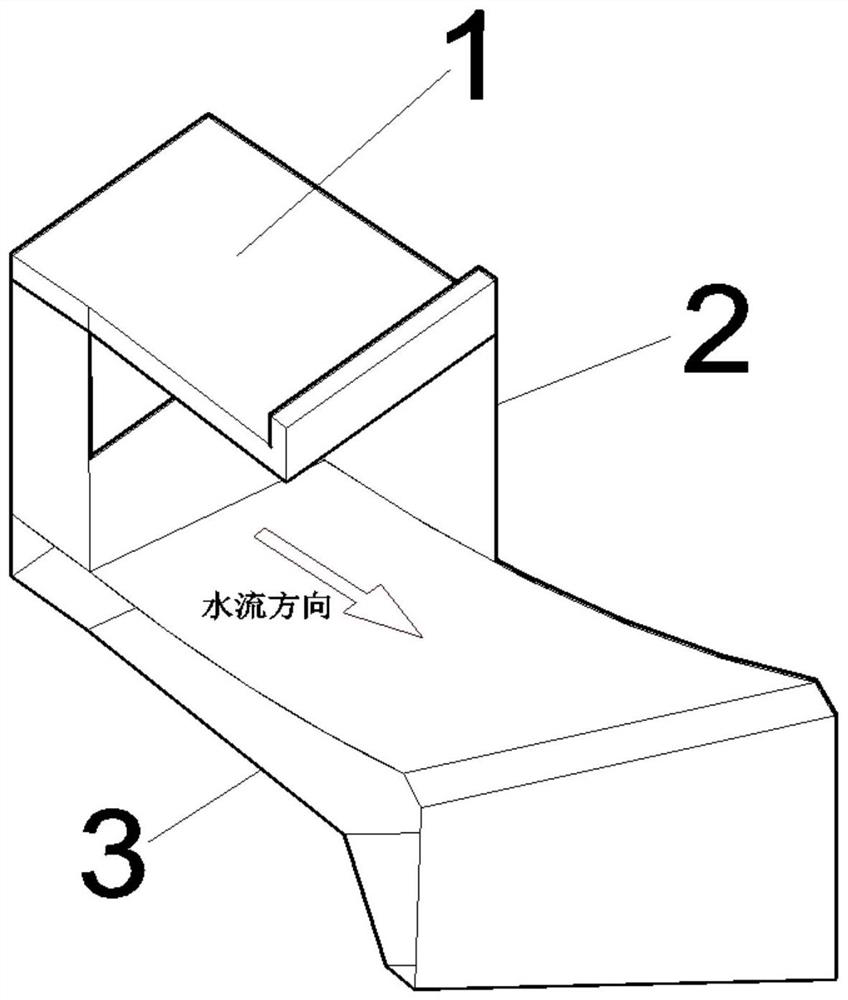
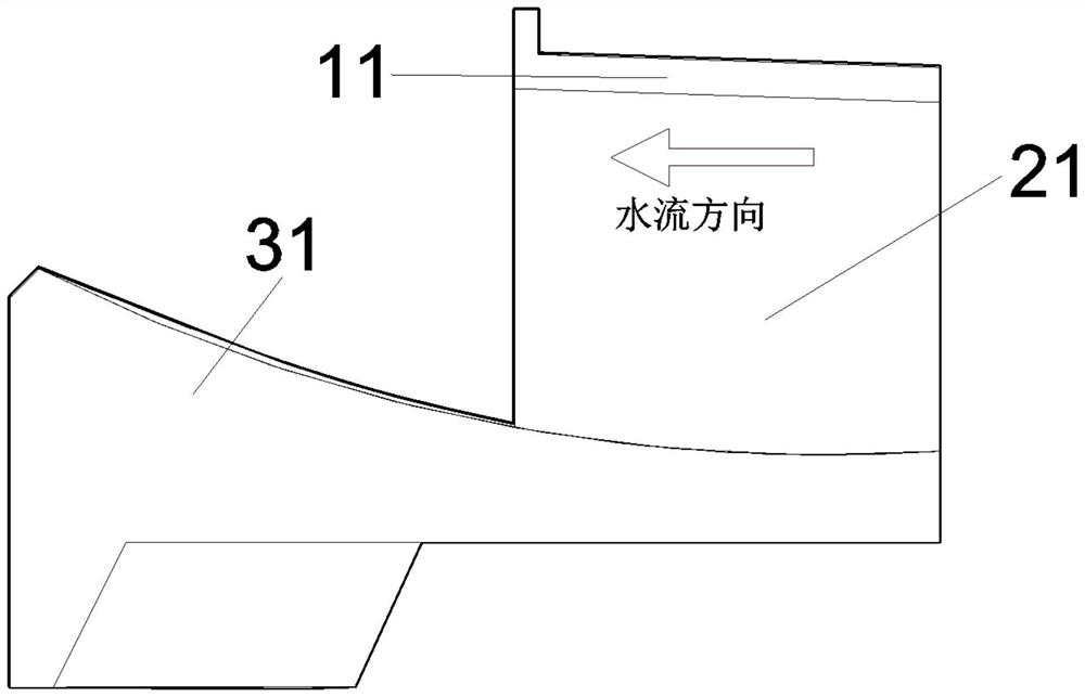
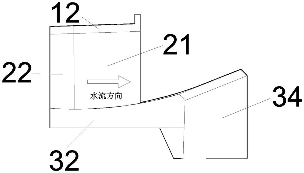
[0031] like figure 1 As shown, the energy-dissipating facility combined with unilateral diffusion and obliquely cut ridges of the present invention includes a ridge top wall 1 , a ridge guide wall 2 , and a ridge base 3 .

[0032] Figure 2 to Figure 7 As shown, the energy-dissipating facilities combined with unilateral diffusion and obliquely cut ridges in this example include a ridge top wall 1 (top wall left side 11, top wall right side 12), two ridge guide walls 2 ( Left pick ridge guide wall 21, right pick ridge guide wall 22) and a pick ridge pedestal 3 (lift ridge base left side 31, pick ridge base right side 32, pick flow nose sill 33; pick ridge base Exit 34), the arc radius of the nose sill is 60m, the angle from the upstream end to the lowest point L of the arc is 3.762°, and the length L of th...


PUM


Abstract

The invention belongs to the technical field of water conservancy and hydropower drainage buildings, and provides a unilateral diffusion and beveled flip bucket combined energy dissipation facility. The unilateral diffusion and beveled flip bucket combined energy dissipation facility comprises a flip bucket top wall, two flip bucket guide walls and a flip bucket base. On one hand, the length and the height of the beveled flip bucket can be flexibly adjusted, the contact area between the water flow and the air in the air is increased and the flow state of the downstream water flow is improved through transverse diffusion and diversion of the beveled flip bucket on the upstream water flow, a stream of water flow with large single-width flow is transversely diffused, and the single-width flow is reduced to a certain extent; and on the other hand, the unilateral diffusion structure abandons the defect that a traditional flip bucket is difficult to control the direction of the flip water flow, the diffusion angle and the offset of the flip bucket are in the critical magnitude, and the atomization effect of the discharged water flow is not prone to affecting surrounding power generation buildings.

Description

technical field [0001] The invention belongs to the technical field of water conservancy and hydropower drainage buildings, and provides an energy dissipation facility combining unilateral diffusion and oblique cutting. Background technique [0002] Among the existing energy dissipation technologies, energy dissipation forms are mainly divided into four types: deflected flow energy dissipation, underflow energy dissipation, surface flow energy dissipation and scoop flow energy dissipation. The advantages of deflected flow energy dissipation are: [0003] 1) The energy dissipation is relatively sufficient, and the falling point of the discharged water is far away from the hydraulic structure, so that the scour of the riverbed by the discharged water will not endanger the safety of the surrounding buildings. [0004] 2) It has a long history, mature technology, simple structure, economical cost, saving investment, strong adaptability, and can be used for large-flow flood disch...

Claims


Application Information

Patent Timeline
Patent Type & Authority Applications(China)
IPC IPC(8): E02B3/06E02B3/10E02B8/06
CPCE02B3/06E02B3/10E02B8/06
Inventor 刘亚坤张帝岑嘉豪吴剑张志强杨姣刘春明张栋邓杨玉刘强佟新郭子君
Owner DALIAN UNIV OF TECH
Why Eureka
Try Eureka