


Quick Research
Generate reliable direction feasibility study reports for your R&D in just a few steps.

Technical Q&A
Discover and master advanced knowledge NOW. Basics, ideas, possibilities, all at once.

Find Solutions
As an expert in R&D theories, this can generate solutions to your technical problems instantly.

Evaluate Feasibility
Analyze your overall solution with one click, know your potential R&D risks in advance.

Monitor Landscape
Get weekly tech updates, stay abreast of the latest tech innovations and key insights.
Mine machining equipment with high protection
A mechanical processing and high-protection technology, applied in cleaning methods and appliances, dust removal, grain processing, etc., can solve problems such as bouncing stones, damage to staff, poor protection effect, etc., to reduce dust flying and improve efficiency , good protective effect
- Summary
- Abstract
- Description
- Claims
- Application Information
AI Technical Summary
Problems solved by technology
Method used
Image

Examples
Embodiment 1
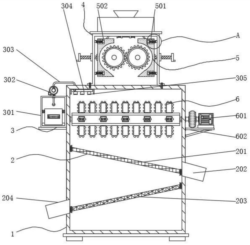
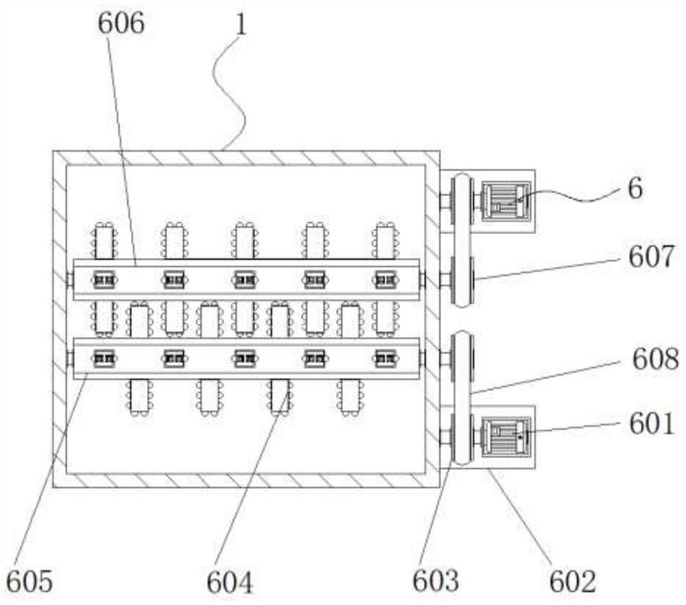
[0044] Example 1; see Figure 1-9 , a mining mechanical processing equipment with high protection, comprising a main body 1, a secondary crushing mechanism 6 is arranged at the top inside the main body 1, a screening structure 2 is arranged at the bottom end inside the main body 1, and the main body 1 A dust removal mechanism 3 is provided on one side, and a feed seat 4 is fixedly connected to the middle position of the top of the equipment main body 1, and a protective structure 5 is provided on both sides of the interior of the feed seat 4. The protective plate 502 that is slidingly connected, the protective plate 502 is symmetrically arranged in two groups, and the two groups of protective plates 502 are connected with threaded rods 21 that are rotated away from the middle of the end, and the threaded rods 21 are threaded through the side wall of the feed seat 4 and fixedly connected There is a turntable 22,
[0045] The upper end of the feed seat 4 is fixedly provided wit...
Embodiment 2
[0050] Embodiment 2: The protective structure 5 also includes a limit groove 501, a limit spring 503, a guide column 504, and a slider 505. The limit spring 503 is provided with two groups and is respectively connected to one of the inside of the feed seat 4. One side and the other side, the slider 505 slides in the limiting groove 501, one side of the limiting spring 503 is fixedly connected to the slider 505, and the limiting groove 501 is fixedly connected to a part inside the protective plate 502. On the side, a guide column 504 is arranged in the middle of the limit spring 503, and both ends of the guide column 504 are fixedly connected with the slider 505 and the side wall of the feeding seat 4, respectively.
[0051] The elastic coefficients of the limiting springs 503 are equal, and the limiting springs 503 are symmetrically distributed about the vertical center line of the feed seat 4;
[0052] Specifically, the protective plate is arranged on both sides of the inside...
Embodiment 3
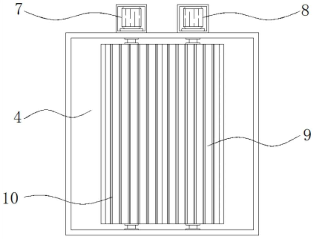
[0053] Embodiment 3: The crushing mechanism includes a second crushing wheel 10, the second crushing wheel 10 is arranged on one side of the feed seat 4, the other side of the second crushing wheel 10 is provided with the first crushing wheel 9, the second crushing wheel One end of 10 is connected to the output end of the first driving motor 7 through a shaft connector, and the first driving motor 7 is fixedly connected to the side of one end of the feeding seat 4. The model of the first driving motor 7 can be ACM, and the first pulverizing One end of the wheel 9 is connected to the output end of the second drive motor 8 through a shaft connector, and the second drive motor 8 is fixedly connected to the other side of one end of the feed seat 4. The model of the second drive motor 8 can be Y90S-2 ;
[0054] The outside of the second pulverizing wheel 10 is provided with tooth blocks equal in size to the outside of the first pulverizing wheel 9, and the second pulverizing wheel ...
PUM
 Abstract
Description
Claims
Application Information
 - R&D Engineer
- R&D Manager
- IP Professional
- Industry Leading Data Capabilities
- Powerful AI technology
- Patent DNA Extraction
Browse by: Latest US Patents, China's latest patents, Technical Efficacy Thesaurus, Application Domain, Technology Topic, Popular Technical Reports.
© 2024 PatSnap. All rights reserved.Legal|Privacy policy|Modern Slavery Act Transparency Statement|Sitemap|About US| Contact US: help@patsnap.com