Special portal crane for wharf panel installation
A gantry crane and panel technology, which is used in cranes, trolley cranes, transportation and packaging, etc., can solve problems such as troublesome back and forth handling, panel falling, inconvenient panel handling, etc., to avoid position offset and ensure balance. Effect
- Summary
- Abstract
- Description
- Claims
- Application Information
AI Technical Summary
Problems solved by technology
Method used
Image
Examples
Embodiment 1
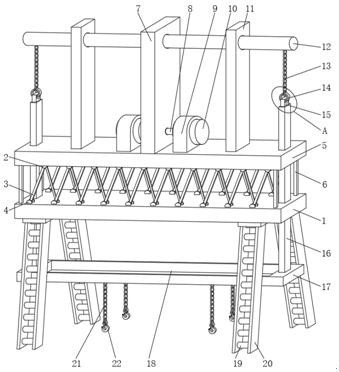
[0031] One embodiment, refer to embodiment Figure 1-7 , Pier panel mounting special gantry crane, comprising a lifting frame 1 One, One lifting frame outer surface of the upper end is provided with a fixing ring 4 II, II stationary inner ring 4 is provided with a rod supporting frame 3, a support rack bar 3 is provided with an outer wall of the fixed ring 2 One, One fixed ring 2 at the lower end surface of the outer boom 5 II, One internal lifting frame 1 is provided with a balanced lifting rod 16, the lifting rod 16 balance the lower end surface of the outer panel is provided with a packing box 17, in order to facilitate the lifting frame 1 and II One lifting frame 5 separated, while facilitating parallel lifting slides balance lever 16, the lifting frame 1 and II One 4 is provided with a fixing ring II One boom between the fixed ring 5, respectively 2, 4 and the fixed ring structure II One same fixed ring 2, provided with internal pole, the bracket 3 is mounted at the first leve...
Embodiment 2
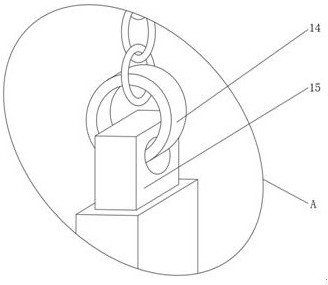
[0034] Example 2, please refer to Figure 1-7 On the basis of the first embodiment, the upper outer surface of the lifting balance rod 16 is provided with auxiliary contact member 15, and the upper end of the auxiliary contact member 15 is provided with a pair of circular ring 14, and the outer surface of the upper end surface of the ring 14 is provided. The heavy chain 13, the first end of the lifting chain 13 is located at the lower end of the lifting wheel 12, and the internal setting of the lifting rod 28 is provided with a balanced door building 11, a winning wheel. The rod 12 is located in the inner wall of the balanced door 11, in order to facilitate the upper and lower movable actuating lifting balance rod 16, the secondary surface of the lifting balance rod 16 is disposed, and the pairing circle 14 passes through the auxiliary pairing 15. The hole, and the opposing rings 14 are hung on the docking rod 28 inside the lifting rod 12, by rotating the hinder rod 12, the one-sta...
Embodiment 3
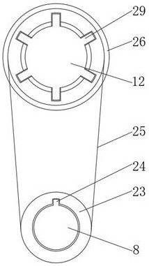
[0037] Example 3, please refer to Figure 1-7 In the basis of the first example and example 2, the upper outer surface of the second layer 5 is provided with two sets of motor fixed tables 9 and a set of heavy door buildings 7, and the lifting door 7 is located in the two sets of motor fixed tables 9 In the interior of each set of motor fixing spaces 9, a set of lifting rector 10 is provided. The inside of the lifting motor 10 is provided with a motor rotor 8, and the outer wall of the motor rotor 8 is provided with a double-docking bomb 24, and the first docking bump 24. The upper end of the line No. 1 pulley 23 is provided with a second pulley 26, and a pulley belt 25 is provided between the No. 1 pulley 23 and the second pulley 26, and the second pulley 26 is located at the outer wall of the lifting wheel 12. The second pulley 26 is located inside the lifting door 7, and the outer wall of the lifting wheel 12 is provided with a second docking bomb 29. In order to facilitate the ...
PUM
 Abstract
Description
Claims
Application Information
 - R&D
- Intellectual Property
- Life Sciences
- Materials
- Tech Scout
- Unparalleled Data Quality
- Higher Quality Content
- 60% Fewer Hallucinations
Browse by: Latest US Patents, China's latest patents, Technical Efficacy Thesaurus, Application Domain, Technology Topic, Popular Technical Reports.
© 2025 PatSnap. All rights reserved.Legal|Privacy policy|Modern Slavery Act Transparency Statement|Sitemap|About US| Contact US: help@patsnap.com


