
Energy storage sub-module and high-voltage large-capacity direct-hanging type energy storage system formed by same

A sub-module and energy storage technology, which is applied in the control/regulation system, electric variable adjustment, output power conversion device, etc., can solve the problem of limiting the parallel scale of energy storage battery packs, and the performance of the chain battery energy storage system cannot meet the requirements of high voltage and high voltage. Capacity and other issues, to avoid uneven charging and discharging current, reduce the pressure of SOC balance, and refine battery management

Pending Publication Date: 2021-10-29
CHINA EPRI ELECTRIC POWER ENG CO LTD
View PDF1 Cites 5 Cited by
  • Summary
  • Abstract
  • Description
  • Claims
  • Application Information

AI Technical Summary

Problems solved by technology

In order to achieve a higher current level for the sub-modules of the chain battery energy storage system, a large number of energy storage battery packs need to be connected in parallel, and the problem of battery circulation after large-scale parallel connection will also limit the parallel scale of the energy storage battery pack
Therefore, due to the above limitations, the performance of the existing chain-link battery energy storage system cannot meet the needs of high voltage and high capacity

Method used


Image

  • Energy storage sub-module and high-voltage large-capacity direct-hanging type energy storage system formed by same
  • Energy storage sub-module and high-voltage large-capacity direct-hanging type energy storage system formed by same
  • Energy storage sub-module and high-voltage large-capacity direct-hanging type energy storage system formed by same

Examples


Embodiment 1

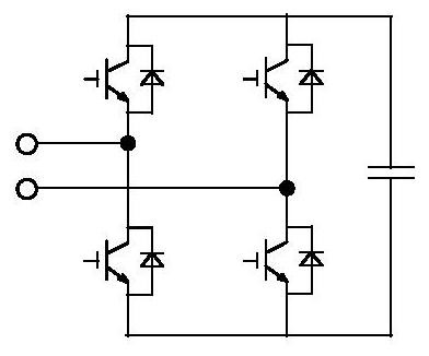
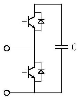
[0064] Under the existing technical conditions, the technical level of power electronic devices can meet the requirements of large-capacity energy storage systems. However, due to the limitations of battery system technology and energy storage system safety design requirements, the voltage and current levels of battery packs that can be constructed currently are all The energy storage sub-module with the battery pack as the basic structure does not meet the requirements (the voltage level of the battery pack is only 600-800V, the highest is only about 1kV, and the capacity of the 0.5C low-rate battery can be up to 300Ah). It will make the energy storage system composed of the sub-modules unable to meet the high-voltage and large-capacity requirements of the energy storage system. Therefore the present invention provides an energy storage sub-module, such as figure 1 As shown, including: MMC converter unit and multiple adjustable DC energy storage units;

[0065] The adjustabl...

Embodiment 2

[0078] The present invention provides an SOC balance control method between adjustable DC energy storage units of an energy storage sub-module, the control block diagram of which is as follows Figure 8 As shown, the specific steps of the method include:

[0079] Step 1: Based on the SOC and DC voltage measured values ​​of each adjustable DC energy storage unit, calculate the current inner loop reference value of each adjustable DC energy storage unit;

[0080] Step 2: Using the current inner loop reference value to determine the current deviation value of each adjustable DC energy storage unit;

[0081] Step 3: Use the current deviation value to control the on-off of the power device of the bidirectional DC / DC conversion unit in each adjustable DC energy storage unit.

[0082] The step 1, the specific steps include:

[0083] Step 1.1: Obtain the SOC of the jth adjustable DC energy storage unit, denoted by SOCj;

[0084] Step 1.2: Obtain the average SOC of the energy storag...

Embodiment 3

[0095] The present invention provides a high-voltage and large-capacity direct-mounted energy storage system composed of the energy storage sub-module described in Embodiment 1, such as Figure 9 As shown, including: A, B and C three-phase;

[0096] Each phase is respectively symmetrically provided with an upper bridge arm and a lower bridge arm, and the upper and lower bridge arms are respectively composed of multiple energy storage sub-modules and an inductor connected in series; the connection point of the upper and lower bridge arms is the input end of the corresponding phase.

[0097] The energy storage system is a double-star structure (three phases A, B and C are connected to the power grid through a double-star connection), and can be directly connected to the 35kV, 220kV, 500kV, or even higher voltage grid without a transformer.


PUM


Abstract

The invention provides an energy storage sub-module and a high-voltage large-capacity direct-hanging type energy storage system formed by the energy storage sub-module. The energy storage sub-module comprises an MMC converter unit and a plurality of adjustable direct-current energy storage units; each adjustable direct current energy storage unit comprises a direct current switch, an energy storage medium unit and a bidirectional DC / DC converter unit; one end of the bidirectional DC / DC converter unit is connected to a series structure of the DC switch and the energy storage medium unit, and the other end of the bidirectional DC / DC converter unit is connected to the DC end of the MMC converter unit; and the energy storage medium unit is formed by connecting a plurality of same energy storage media in series. The high-voltage large-capacity direct-hanging type energy storage system comprises each phase branch composed of an inductor and a plurality of energy storage sub-modules. The DC / DC multiple technology is adopted for capacity expansion on the direct current side of the energy storage sub-module, the problem that the current level of the energy storage medium unit is low is solved, each bidirectional DC / DC conversion unit can independently adjust the current flowing through the corresponding energy storage medium unit, the phenomenon that charging and discharging currents between the energy storage medium units are not uniform is avoided, while battery management is refined, the pressure of SOC equalization is greatly reduced.

Description

technical field [0001] The invention relates to the technical field of power electronics, in particular to an energy storage sub-module and a high-voltage and large-capacity direct-mounted energy storage system composed of the same. Background technique [0002] With the rapid development of power electronics technology and the maturity of distributed power generation technology, the proportion of renewable energy such as solar energy, wind energy, and tidal energy in traditional power grids is gradually increasing. [0003] Renewable energy itself has the characteristics of volatility and randomness, which will have an impact on the peak load regulation of the power grid and the safe and reliable operation of the system. As an important link in the power grid, energy storage technology has fast response characteristics and flexible charging and discharging capabilities. Effectively stabilize system power fluctuations and improve the stability and predictability of renewable...

Claims


Application Information

Patent Timeline
Patent Type & Authority Applications(China)
IPC IPC(8): H02J7/06H02J7/00H02J3/32H02J3/38H02J3/36H02M3/158H02M3/335H02M1/088H02M1/12
CPCH02J7/06H02J7/0019H02J7/0048H02J7/0029H02J3/32H02J3/38H02J3/36H02M3/1582H02M3/3353H02M1/088H02M1/12H02J2207/20Y02E60/60
Inventor 查鲲鹏燕翚杨岳峰詹雄朱宁辉季建辉张加林
Owner CHINA EPRI ELECTRIC POWER ENG CO LTD
Learn More