Hydraulic-based concrete-filled steel tube hooping effect testing device
A technology for concrete filled steel tubes and testing devices, which is applied to measuring devices, force/torque/work measuring instruments, instruments, etc., can solve problems such as large measurement errors, and achieve difficult installation, small scouring area, economical and practical effects
- Summary
- Abstract
- Description
- Claims
- Application Information
AI Technical Summary
Problems solved by technology
Method used
Image

Examples
Embodiment 1
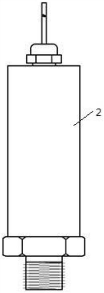
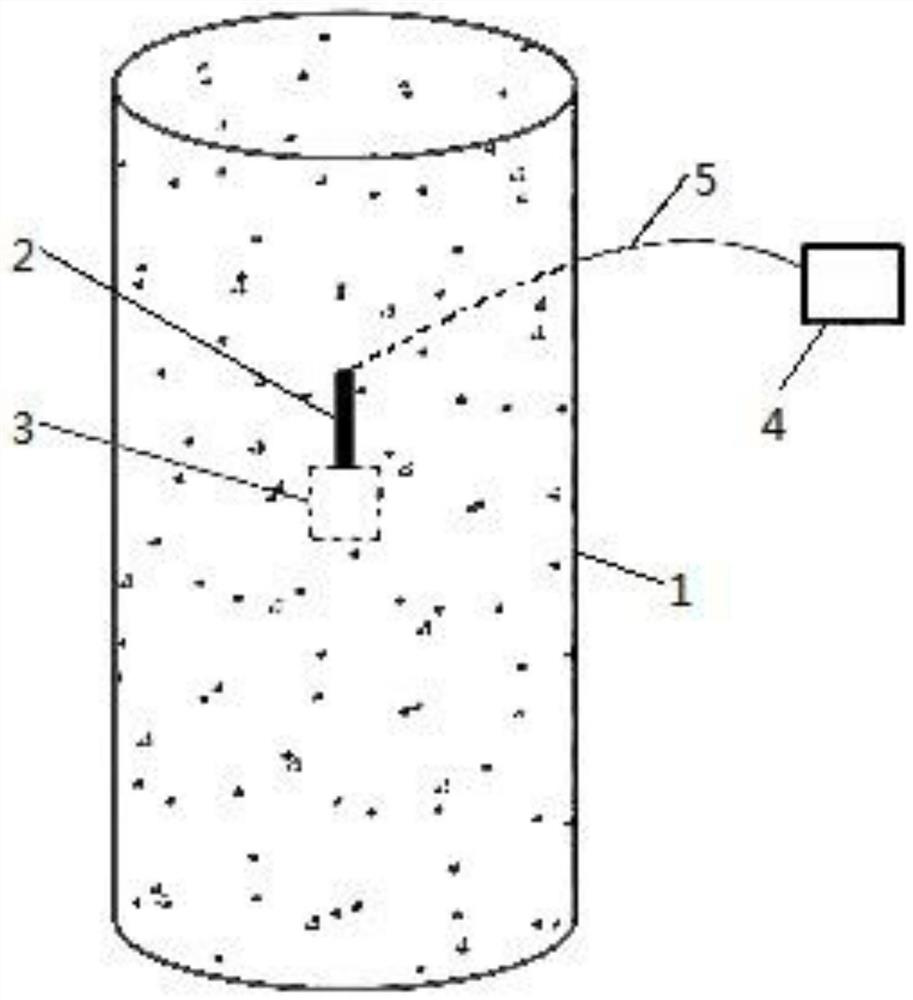
[0033] A hydraulic-based test device for the hoop action of concrete filled steel tubes, such as figure 1 , figure 2 , Figure 4 , including a hydraulic pressure sensor 2 and a storage unit 3 for containing liquid (such as water, suspension mixed with different substances, emulsion, colloid, etc.) or gas (such as air, etc.), and the storage unit 3 is set on the steel pipe 1 On the inner wall (for example, by bonding or through the intermediate card seat limit connection, etc.), the outlet on the storage part 3 is in sealing connection with the interface of the hydraulic sensor 2 . In this embodiment, the outer diameter of the steel pipe 1 is 325mm and the thickness is 6mm.
[0034] Wherein, the installation direction of the storage part 3 on the inner wall is not limited to the axial and circumferential direction of the steel pipe, and can also be arranged obliquely. Preferably, under the premise that the storage part 3 has a large enough hole diameter to be suitable for c...
Embodiment 2
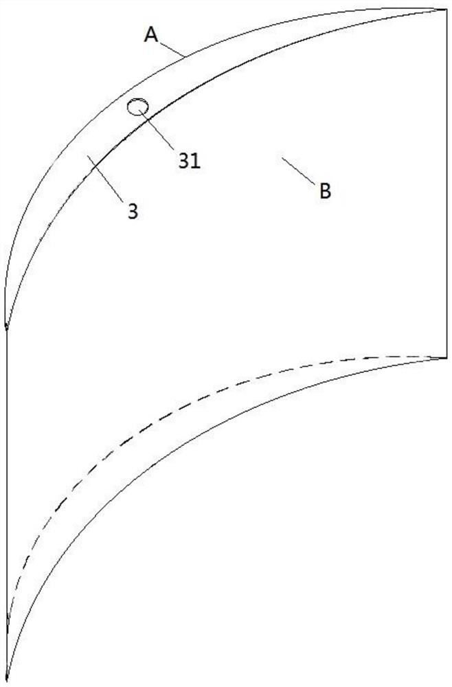
[0040] As a specific implementation, such as figure 2 , image 3 , the storage part 3 in the above-mentioned embodiment 1 includes two connected side surfaces, and a top surface and a bottom surface connecting the two sides, wherein an opening 31 is provided on the top surface, and the opening 31 is used to adapt to the interface of the hydraulic pressure sensor 2 connect. Further, the storage part 3 is preferably designed in the shape of a tile, about the size of a palm, about 8 cm long, and about 5 cm wide; the opening 31 is set toward the axial direction of the steel pipe 1, and both sides are arc surfaces—A side and B side surface, wherein the curvature of the arc surface near the steel pipe 1 side is consistent with the curvature of the inner wall arc surface of the steel pipe 1 (in this embodiment, the A surface is designed as an arc surface with the same radius as the inner wall of the steel pipe 1, and the B surface is slightly larger than the inner wall radius of th...
Embodiment 3
[0043] As a specific implementation, such as Figure 4 , Figure 5 , the storage part 3 in the above-mentioned embodiment 1 is a pipeline structure with one end sealed and the other end matched with the hydraulic sensor 2, wherein the cross-sectional form of the pipeline structure is not limited to a circle, and can also be ellipse, triangle, rectangle, trapezoid Equivalent geometric shapes; the interior of the storage part 3 is filled with liquid. The pipe is located on the inner wall of the steel pipe 1 and arranged in an S-shaped continuous bend along the circumferential direction. Specifically, the pipe continuously bent includes several vertical parts and corresponding curved parts connecting adjacent vertical parts. The vertical parts are arranged along the axial direction of the steel pipe 1. , the pipe extends and bends toward the steel pipe 1 circumferentially, ensuring that the pipe and the inner wall of the steel pipe 1 have a large contact surface for a firm conne...
PUM
 Abstract
Description
Claims
Application Information
 - R&D
- Intellectual Property
- Life Sciences
- Materials
- Tech Scout
- Unparalleled Data Quality
- Higher Quality Content
- 60% Fewer Hallucinations
Browse by: Latest US Patents, China's latest patents, Technical Efficacy Thesaurus, Application Domain, Technology Topic, Popular Technical Reports.
© 2025 PatSnap. All rights reserved.Legal|Privacy policy|Modern Slavery Act Transparency Statement|Sitemap|About US| Contact US: help@patsnap.com