Rotary compressor, refrigerating circulation and ice house using same

A rotary compressor and compressor technology, applied in the field of refrigerators, can solve the problems of sliding and reliability reduction of the guide groove 17, instability at the moment of movement, and increased sliding loss, so as to avoid the concentration of load and prevent sliding Loss, effect to prevent rise in temperature

Inactive Publication Date: 2004-01-21
MITSUBISHI ELECTRIC CORP
View PDF1 Cites 1 Cited by
  • Summary
  • Abstract
  • Description
  • Claims
  • Application Information

AI Technical Summary

Problems solved by technology

Since the fulcrum is not in one place as mentioned above, the fulcrum is at Figure 10A status and Figure 10B Problems such as instability, sliding of the guide groove 17, and reduced reliability occur at the moment of movement between states
[0021] If the motion space 5a of the blade is opened in the airtight container 13, due to the increase or decrease of the volume of the motion space of the blade, problems such as loss and unstable fulcrum of the guide groove can be avoided. When the airtight container 13 is the discharge pressure, as Figure 11 As shown, the pressure in the moving space 5a of the vane is the discharge pressure Pd, the fulcrums S and S' of the guide groove 17 are close to the inner circumference of the cylinder, and the loads F3 and F3' between the plane part of the guide groove and the side of the vane are concentrated on the On the narrow part of the inner circumference of the cylinder, not only the sliding loss is increased, but also the reliability is reduced
[0022] In addition, when a discharge pressure atmosphere is formed in the airtight container 13, if a flammable refrigerant such as a hydrocarbon-based refrigerant (HC refrigerant) is used, the space in the airtight container becomes a high-pressure part, and the discharge of the circuit volume in motion If the pressure part increases, the oil accumulated in the airtight container will be exposed to the discharge pressure, and the amount of refrigerant dissolved in the oil will increase compared with the suction pressure atmosphere, thereby increasing the amount of refrigerant sealed in the circuit. These phenomena Considering the relationship with ignition and explosion and safety considerations, it is undesirable to appear
In addition, from the viewpoint of reducing the amount of sealed refrigerant, it is desirable that the space volume in the airtight container be as small as possible, but in the reciprocating compressor that sucks the atmosphere of pressure mist in the airtight container, if Figure 12 As shown, since it is an asymmetrical structure with piston 15a and cylinder 5 arranged only in one direction relative to the center of the motors 1, 2 and drive shaft 6, resulting in a part of the internal space volume of the non-compression mechanism part increase

Method used


Image

  • Rotary compressor, refrigerating circulation and ice house using same
  • Rotary compressor, refrigerating circulation and ice house using same
  • Rotary compressor, refrigerating circulation and ice house using same

Examples


Embodiment approach 1

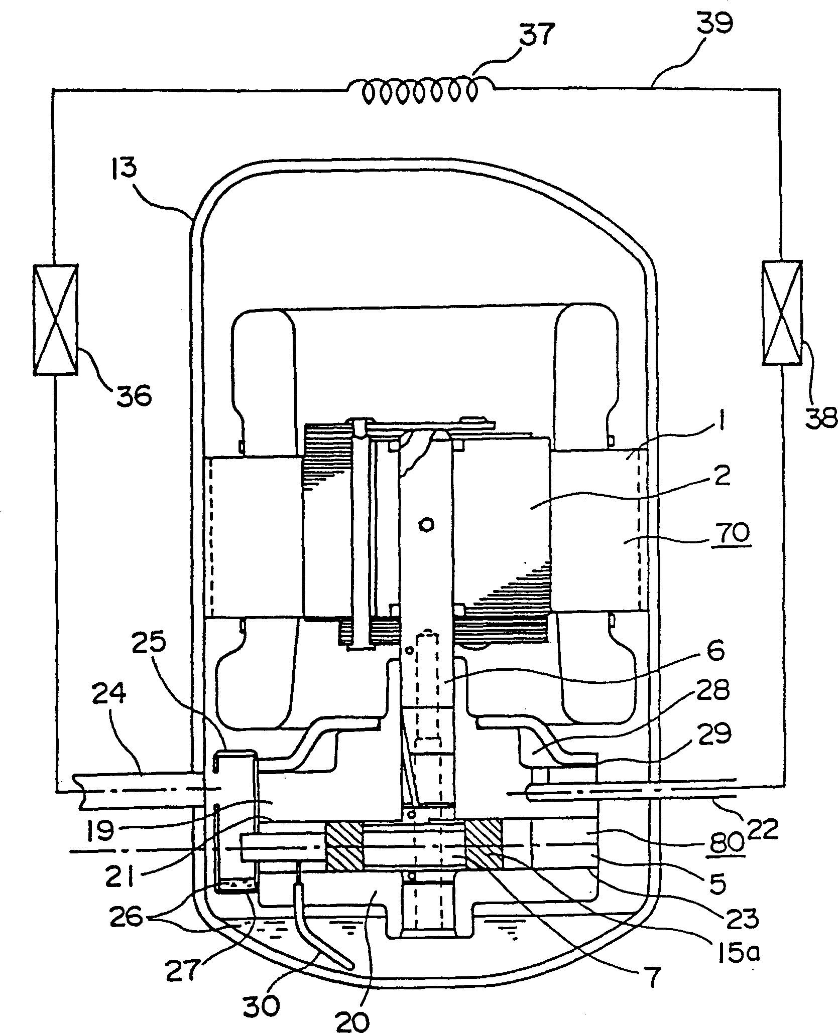
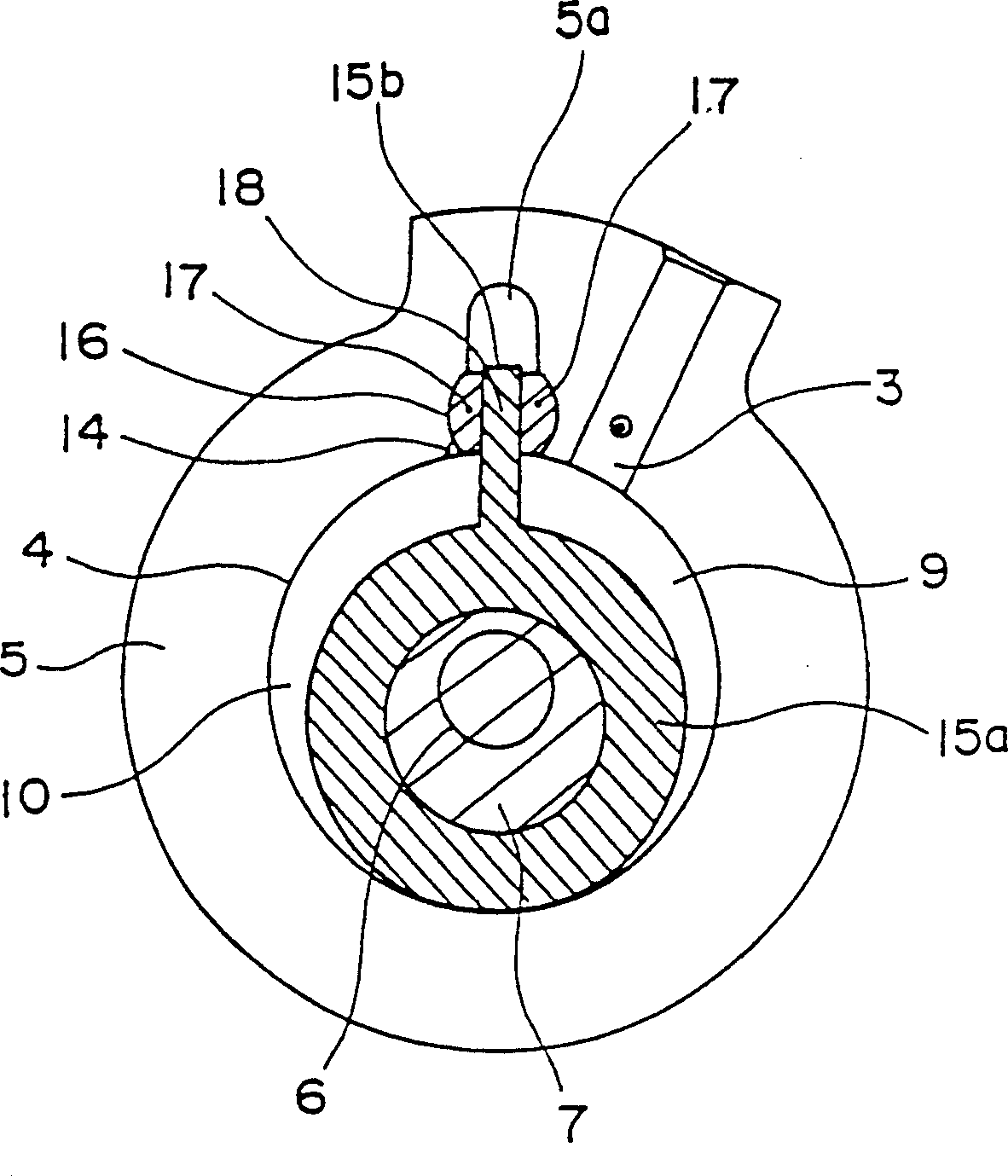
[0068] figure 1 It is a vertical sectional view and a refrigeration cycle diagram of a vane-integrated piston type rotary compressor in an embodiment of the present invention, figure 2 It is a cross-sectional view of the compression mechanism part of the same compressor.

[0069] In the figure, the vane-integrated piston type rotary compressor includes a motor unit 70 composed of a stator 1 and a rotor 2 , and a compression mechanism unit 80 driven by the motor unit 70 . Compression mechanism part 80 comprises: cylinder 5, and it has a cylinder room 4, and suction port 3 and discharge port 14 are opened on this cylinder room 4; 7 and can freely rotate around it; the blade 15b divides the cylinder chamber 4 designed as one with the piston 15a into two parts: the low-pressure chamber 9 communicated with the suction port 3 and the high-pressure chamber 10 communicated with the discharge port 14; the guide groove 17, is embedded in the cylindrical hole 16 formed in the cylinde...

Embodiment approach 2

[0083] In this embodiment, the same parts as those in the first embodiment are denoted by the same symbols, and their descriptions are omitted, and only the characteristic parts of this embodiment will be described. Fig. 4A is a longitudinal sectional view of the vane-integrated piston type compressor of the present embodiment, showing elastic support members; Fig. 4B is a longitudinal sectional view and refrigeration cycle diagram of the same compressor of the present embodiment, showing the suction path and spit out the path. In FIGS. 4A and 4B , the vane-integrated piston type compressor includes a motor unit 70 composed of a stator 1 and a rotor 2 , and a compression mechanism unit 80 driven by the motor unit 70 . and in Embodiment 1 figure 2 The same as shown, the compression mechanism part 80 includes: a cylinder 5, which has a cylinder chamber 4, the suction port 3 and the discharge port 14 are opened on the cylinder chamber 4; the piston 15a is installed in the above...

Embodiment approach 3

[0092] Embodiment 3 of the present invention will be described below. The vane-integrated piston type rotary compressor in this proposal is a vane-integrated piston type rotary compressor constructed as in Embodiment 1 and Embodiment 2, wherein HFC-based refrigerants such as R134a are used as refrigerants.

[0093] In the vane-integrated piston type rotary compressor constituted according to the above scheme, since the airtight container is a suction pressure atmosphere, there is no high-temperature and high-pressure gas refrigerant flowing from the contact surface between the cylinder and the frame and the contact surface between the cylinder and the cylinder head, The phenomenon of reverse flow to the low-pressure side equipped with the evaporator, so that there is no need to specially set a check valve in the circuit to prevent the temperature rise of the cooler during the running gap. In addition, since the vane is integrated with the piston, problems such as failure to st...


PUM


Abstract

A rotary compressor having a piston provided integrally with a blade is contained in a hermetic vessel which is operated at a suction pressure of the rotary compressor and not to discharge pressure. The rotary compressor includes a compression mechanism portion having a cylinder which includes a suction port formed in a cylinder chamber, a piston which eccentrically revolves in the cylinder, a blade which is integrally formed with the piston and partitions the cylinder chamber into a high pressure chamber and a low pressure chamber, and a driving shaft for revolving the piston. The rotary compressor also includes an electric motor portion for rotating the driving shaft, a hermetic vessel which houses the compression mechanism portion and the electric motor portion and is in communication with the suction port thereby to maintain an interior of the hermetic vessel at a suction pressure atmosphere, and a discharge port formed in the cylinder chamber and in direct communication with an exterior of the hermetic vessel, whereby starting is smoothly performed, a motor having a large starting torque is not required, components such check valves can be avoided, and lubricating oils with stable viscosity can be used such that the compressor operates with environmentally-friendly refrigerants.

Description

technical field [0001] The present invention relates to a rotary compressor having a piston integrally designed with vanes, a refrigerating cycle performed in a refrigeration device, an air conditioner, etc. using the compressor, and a refrigerator using the compressor. Background technique [0002] Figure 5 , 6 A rolling piston type rotary compressor (in this example, a 2-cylinder rotary compressor) in the prior art is shown, such as the one disclosed in Japanese Patent Publication No. 2502756. Figure 5 is the longitudinal section view of the compressor and the refrigeration cycle diagram, Figure 6 It is a cross-sectional view of the compression mechanism part of this compressor. Refer to the following Figure 5 , Figure 6 Be explained. A conventional rotary compressor includes a motor unit 50 and a compression mechanism unit 60 composed of a stator 1 and a rotor 2 . This compression mechanism part 60 is driven by this motor part 50, comprises: frame 19; Cylinder 5,...

Claims


Application Information

Patent Timeline
Patent Type & Authority Patents(China)
IPC IPC(8): F04C18/32F04C23/00
CPCF04C18/322F04C2240/603F04C23/008
Inventor 角田昌之渡边英治小川喜英石井稔谷真男郡嶋宗久山本隆史川口进
Owner MITSUBISHI ELECTRIC CORP
Why Eureka
Try Eureka