Flue gas denitration ammonia spraying mixing system and static mixer and ammonia spraying control method thereof

A static mixer and mixing system technology, applied in the field of flue gas denitrification, can solve the problems of large concentration gap, poor uniformity of ammonia injection, difficult to reflect truthfully, etc., and achieve the effects of increasing particle size, prolonging service life and avoiding wear and tear.

Active Publication Date: 2021-10-22
CHINA PETROLEUM & CHEM CORP +1
View PDF7 Cites 2 Cited by
  • Summary
  • Abstract
  • Description
  • Claims
  • Application Information

AI Technical Summary

Problems solved by technology

Since it takes a long time to adjust the uniformity of ammonia spraying every time it is started and has high technical content, the SCR denitrification device is generally entrusted to a professional company to adjust it when it is started. After the adjustment is completed, the opening of the ammonia injection manual control valve is no longer adjusted
[0008] Existing SCR inlet and outlet NO x Concentration detection generally adopts single-point measurement, and the monitoring point is generally set in the center of the flue, but the same cross-section of the flue NO x The concentration gap is quite large, and the representativeness of single-point detection is poor, so it is difficult to reflect NO truthfully. x The average concentration; when the load of the device, the combustion method, and the type of coal to be burned change, the distribution of the flue gas flow field in the flue changes under different working conditions, and the NO in the flue gas x The concentration distribution also changed. The opening of the ammonia injection manual control valve set when the device was started could no longer meet the requirements under other working conditions. The uniformity of ammonia injection became worse, and the deviation between the ammonia nitrogen molar ratio and the average value in local areas became larger. Areas where the molar ratio is too small have low denitrification efficiency and export NO x Unable to reach the standard, the area where the ammonia nitrogen molar ratio is too large ammonia escape exceeds the standard
As the country pays more attention to environmental protection, local environmental protection bureaus x Penalties for exceeding the standard are gradually increasing, as the Environmental Protection Agency has imposed strict regulations on NO x The concentration is monitored dynamically in real time, and the value of ammonia escape has not yet been included in the monitoring range. In order to ensure environmental protection standards, companies generally increase the amount of ammonia sprayed to discharge the flue gas out of NO x Control in a lower range, resulting in a substantial increase in ammonia escape from the SCR denitrification device, resulting in corrosion leakage or serious blockage of rear-end air preheaters or economizers and other equipment. If there is a wet desulfurization device in the future, it will also cause ammonia nitrogen content in the desulfurization wastewater. Significantly exceeded

Method used


Image

  • Flue gas denitration ammonia spraying mixing system and static mixer and ammonia spraying control method thereof
  • Flue gas denitration ammonia spraying mixing system and static mixer and ammonia spraying control method thereof
  • Flue gas denitration ammonia spraying mixing system and static mixer and ammonia spraying control method thereof

Examples


Embodiment 1

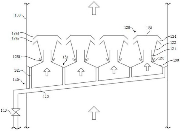
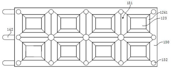
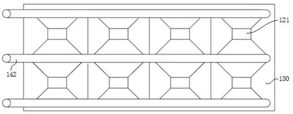
[0084] refer to Figure 1~3 As shown, the static mixer of the present embodiment is a single layer, which includes eight guide assemblies 120, and the guide assembly 120 consists of an air inlet pipe 121, an outer pipe 122, a top plate 123, four upper wing plates 1241 and four lower wings. Board 1242 composition. The air intake pipe 121 is a straight pipe, the cross section of the outer pipe 122 is rectangular, and the upper wing plate 1241 and the lower wing plate 1242 are trapezoidal. The dust discharge hole 125 communicates with an upwardly inclined dust discharge pipe 1251 , and the lower end surface of the outlet of the dust discharge pipe 1251 is higher than the upper end surface of the dust discharge hole 125 . Ash collecting groove is V-shaped groove 131. In the ash discharge pipe 140, three rows of first vertical sections 141 are respectively connected to three discharge pipe sections 142 to discharge dust. An on-off valve 143 is provided for regular ash discharge....

Embodiment 2

[0087] refer to Figure 4~6 As shown, the static mixer of the present embodiment is a single layer, which includes thirty-two guide assemblies 220, and the guide assembly 220 is composed of an air inlet pipe 221, an outer pipe 222, a top plate 223, an upper wing plate 2241 and a lower wing plate 2242. composition. The air inlet pipe 221 is a variable-diameter round pipe with a thick bottom and a thin top. The cross section of the outer pipe 222 is circular, the top plate 223 is inverted conical, and the upper wing 2241 and the lower wing 2242 are truncated cones. The dust discharge hole 225 communicates with a downwardly inclined dust discharge pipe 2251 , and the outlet of the dust discharge pipe 2251 is provided with a first cover plate 2252 . The ash collecting trough is an arc groove 231, and the notch is provided with a windshield 2311, one end of the windshield 2311 is connected with the outer pipe 222, and the other end extends downwards, leaving a gap between the wind...

Embodiment 3

[0090] refer to Figure 7 As shown, the static mixer of the present embodiment has two layers, wherein the structure of the static mixer of the lower floor is the same as that of Example 2; the structure of the static mixer of the upper floor is basically the same as that of Example 1. The pipeline is changed from three rows of first vertical sections to five rows of first vertical sections, which are respectively connected with five discharge pipe sections. The discharge pipes on the upper layer and the lower layer are respectively connected to five second vertical sections 344 to discharge the dust, and the second vertical sections 344 are provided with a second cover plate 345 for automatic ash discharge.

[0091] The flue gas of a coal-fired boiler adopts the double-layer static mixer of this embodiment. Along the flow direction of the flue gas, the content of particulate matter (dust) before the static mixer is 2272mg / Nm 3 , the particle (dust) content after the static m...


PUM


Abstract

The invention discloses a static mixer which is arranged in a flue, the static mixer comprises a plurality of flow guide assemblies distributed in the flue, and each flow guide assembly comprises a gas inlet pipe extending in the axial direction of the flue, a gas outlet pipe extending in the axial direction of the flue, and a gas outlet pipe extending in the axial direction of the flue; the outer pipe is of a tubular structure with a thin lower part and a thick upper part, the lower end of the outer pipe is connected with the outer wall of the air inlet pipe, and the upper end is higher than the air inlet pipe; the top plate is arranged above the outer pipe; the air outlet channel obliquely extends downwards from the periphery of the top end of the outer pipe; the dust discharging hole is formed in the lower end of the outer pipe; and the ash collecting layer is in sealed connection with the inner wall of the flue, and an ash collecting groove is formed between the flow guide assemblies. The invention further discloses a flue gas denitration ammonia spraying mixing system and an ammonia spraying control method thereof. By arranging the flow guide assembly, two-time flue gas dust removal is achieved, and dust particles with large particle sizes in flue gas can be effectively removed; the static mixer disclosed by the invention can also effectively block large dust falling from the flue above, so that an ammonia gas nozzle below is prevented from being blocked.

Description

technical field [0001] The invention relates to the technical field of flue gas denitrification, in particular to a flue gas denitrification ammonia injection mixing system, a static mixer thereof, and an ammonia injection control method. Background technique [0002] At present, among the flue gas denitrification methods, the most widely used is the selective catalytic reduction (SCR) denitrification technology. The main principle of SCR denitrification technology is to spray the reducing agent ammonia into the flue gas at 280 ° C ~ 420 ° C and mix it evenly. Under the action of the catalyst, NH 3 NO in flue gas x Reduce to non-toxic, non-polluting nitrogen and water, so as to realize the removal of NO from mixed gas x the goal of. [0003] Flue gas denitrification efficiency and NH 3 Escape rate is the two core performance indicators of SCR denitrification technology. Studies have shown that the flow field uniformity of the mixed gas on the cross section of the SCR re...

Claims


Application Information

Patent Timeline
Patent Type & Authority Applications(China)
IPC IPC(8): B01D53/86B01D53/56B01D53/76B01D53/34
CPCB01D53/8628B01D53/76B01D53/346B01D2258/0283B01D2251/2062Y02C20/10
Inventor 李磊李欣金平韩天竹李睿高峰
Owner CHINA PETROLEUM & CHEM CORP
Why Eureka
Try Eureka