
Production line for producing electric igniter support

An electric ignition head and production line technology, which is applied in the field of electric ignition head production and production line production of electric ignition head brackets, can solve the problems of high labor intensity, affecting product performance, unreliable safety of manual drug packaging, etc., and achieves welding speed and The effect of quality improvement, high product quality stability, and controllable solder joint size

Active Publication Date: 2021-10-19
四川仲玛智造科技有限公司
View PDF7 Cites 3 Cited by
  • Summary
  • Abstract
  • Description
  • Claims
  • Application Information

AI Technical Summary

Problems solved by technology

[0003] At present, the welding of the electric ignition head bracket is manual welding. The fatal weakness of manual soldering is that the welding quality is unstable, which affects product performance, low production efficiency, and high labor intensity. Operators have to work under high tension for a long time
According to statistics, even workers with eyesight of 1.5 will experience a sharp decline in vision a few years after taking up the job, and it is difficult to maintain a long-term stable team of skilled workers on the production line, thus limiting the development of electrical explosive products to a certain extent
[0004] The existing entire process of dipping the drug is manually dipped in the drug, but the manual operation has the following disadvantages: the manual operation process is uncontrollable; the manual cleaning of the electric ignition head bracket is not in place, resulting in unqualified products after the drug is packaged; The amount of medicine is not easy to control, and relevant data on product production cannot be formed; the surface color of the medicine head is uneven, with air bubbles, shrinkage cavities, and blocks after manual medicine packaging; the safety of manual medicine packaging is unreliable

Method used


Image

  • Production line for producing electric igniter support
  • Production line for producing electric igniter support
  • Production line for producing electric igniter support

Examples


Embodiment 1

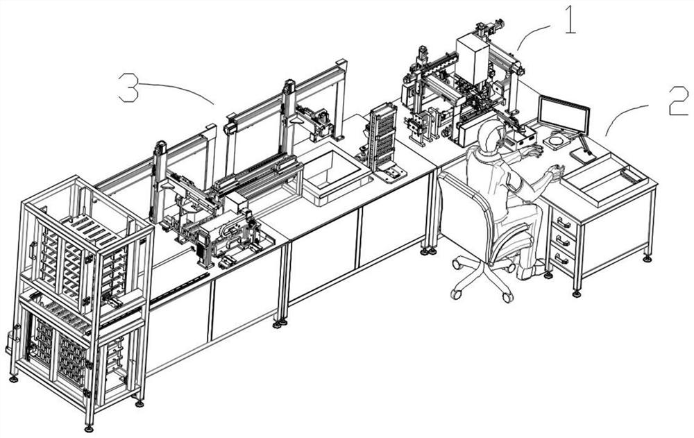
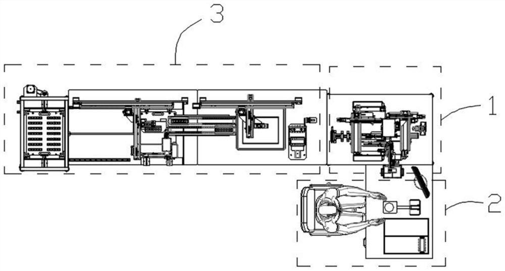
[0055] Such as Figures 1 to 23 As shown, the present embodiment provides a production line for producing electric ignition head brackets, including an automatic welding system 1 for welding the foot line and bridge wire on the toothed sheet, manual assistance for loading the welded toothed sheet into the frock System 2. The automatic drug-dipping forming system of the electric ignition head bracket that realizes the formation of the drug-packed tooth-shaped sheet in the tooling. 3. The control system for controlling the automatic welding system 1 and the automatic drug-dipping forming system 3. The automatic welding system 1 and The automatic drug-dipping forming system 3 is electrically connected with the control system.

[0056] The control system adopts the upper computer and the SCADA system based on PLC control.

[0057] The manual auxiliary system is mainly composed of a manual operation platform, a host computer, and manual auxiliary processing bridge wire equipment. ...

Embodiment 2

[0059] This embodiment is further optimized on the basis of implementation 1, specifically:

[0060] The automatic welding system 1 includes a welding frame 1-1 and a material turning mechanism 1-6 for pushing and flipping the toothed sheet, and a foot for actively outputting the foot line, which are all installed on the welding frame 1-1. Thread constant tension wire feeder 1-7, bridge wire constant tension wire feeder 1-2 for actively outputting bridge wire, wire pulling mechanism 1-5 for pulling and cutting foot wire and bridge wire, handle wire The laser welding system 1-4 welded on the toothed sheet with the bridge wire, the toothed sheet shearing machine 1-3 for cutting the welded toothed sheet to form an electric ignition head, and the toothed sheet shearing machine 1-3 Coordinated electric ignition head off-line mechanism 1-8, resistance detection system 1-10 for detecting the resistance of toothed sheet, and smoke dust processing device 1-9 for processing smoke dust. ...

Embodiment 3

[0073] This embodiment is further optimized on the basis of implementing 1 or 2, specifically:

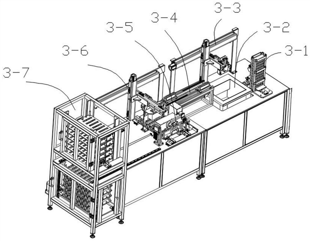
[0074] The automatic drug-dipping forming system 3 includes an installation platform and a tooling feeding mechanism 3-1, a cleaning tank 3-2, a transfer mechanism A3-3, a transfer mechanism B3-4, and a drug-dipping plastic mechanism 3 arranged sequentially on the installation platform. -5. Carrying mechanism C3-6 and automatic drying frame 3-7.

[0075] The drug-dipping plastic mechanism 3-5 includes a drug-dipping mold assembly 3-5.2, a liftable drying mechanism 3-5.3 arranged below the drug-dipping mold assembly 3-5.2, and a liftable drying mechanism 3-5.3 arranged on one side of the drug-dipping mold assembly 3-5.2 A dispensing machine 3-5.1 for pouring medicine into the medicine dipping mold assembly 3-5.2, said medicine dipping mold assembly 3-5.2 including a mounting bracket, a mold that can be opened and closed on the mounting bracket, and a dispensing device that drives th...


PUM


Abstract

The invention discloses a production line for producing an electric igniter support, and relates to the technical field of electric igniter production. The production line comprises an automatic welding system for welding a leg wire and an igniter wire on a tooth-shaped sheet, a manual auxiliary system for loading the welded tooth-shaped sheet into a tool, an automatic powder dipping and forming system for the electric igniter support formed by dipping the tooth-shaped sheet in the tool with powder, and a control system for controlling the automatic welding system and the automatic powder dipping and forming system, wherein the automatic welding system and the automatic powder dipping and forming system are electrically connected with the control system; and the production line is simple in structure, welding automation and powder dipping automation of the whole electric igniter support are achieved, and the welding speed and quality are remarkably improved.

Description

technical field [0001] The invention relates to the technical field of electric ignition head production, and more specifically relates to the technical field of production lines for producing electric ignition head brackets. Background technique [0002] Electrical explosives are a general term for disposable components and devices that are filled with gunpowder or explosives and burn or explode after being stimulated by the outside to ignite gunpowder, detonate explosives or perform mechanical work. The electric ignition head is a kind of ignition product. During the processing of the electric ignition head bracket, it is necessary to weld the leg line and bridge wire of the tooth-shaped sheet and dip the welded tooth-shaped sheet to form it. [0003] At present, the welding of the electric ignition head bracket is all manual welding. The Achilles heel of manual soldering is that the welding quality is unstable, which affects product performance, low production efficiency,...

Claims


Application Information

Patent Timeline
Patent Type & Authority Applications(China)
IPC IPC(8): F42B33/00F42B3/195B23P23/00B23K26/21B23D15/06
CPCF42B33/00F42B33/002F42B3/195B23P23/00B23K26/21B23D15/06
Inventor 付仲赵俊铭杨煜侯开祥黄琦琦胥勋泽
Owner 四川仲玛智造科技有限公司
Learn More