Built-in circuit structure of CO2 fracturing device

A circuit structure and cracker technology, which is applied in the direction of weapon accessories, offensive equipment, blasting barrels, etc., can solve the problems of substandard sealing effect of bursting discs, hidden dangers of engineering construction safety, unstable circuits, etc., and solve the problem of poor internal power supply, Avoid line wear and ensure free flow

Active Publication Date: 2021-10-19
HENAN POLYTECHNIC UNIV +3
View PDF9 Cites 0 Cited by
  • Summary
  • Abstract
  • Description
  • Claims
  • Application Information

AI Technical Summary

Problems solved by technology

Currently CO 2 There are many ways to connect the cracker to the circuit, such as insulating the bursting disc to make the carbon dioxide cracking tube non-conductive, and soldering wiring devices on both sides of the bursting disc, but this method can easily cause circuit instability and thus cause misfiring
Also CN111595205A describes another series connection method, in which a threading hole is provided on the rupture disc to allow the wire to pass through, but in order to ensure that the internal pressure reaches a predetermined pressure value, the CO 2 The cracker can cause cracks, and the thickness of the bursting disc is designed to be certain. Once a hole is opened on the bursting disc, it is difficult to control the predetermined pressure and the sealing effect of the hole is difficult to guarantee. Casualties are likely to occur during construction
[0004] The disc bursting disc with the traditional shear failure mechanism has a close relationship between the burst pressure of the CO2 cracker and the thickness of the bursting disc and the shear strength of the material. To increase the pressure of the bursting disc, it is necessary to increase the thickness of the bursting disc, which leads to CO2 During the use of the cracker, due to the thickness of the bursting disc, there is a problem of early or delayed pressure relief and sealing, which brings huge safety hazards to the engineering construction

Method used


Image

  • Built-in circuit structure of CO2 fracturing device

Examples


Embodiment 1

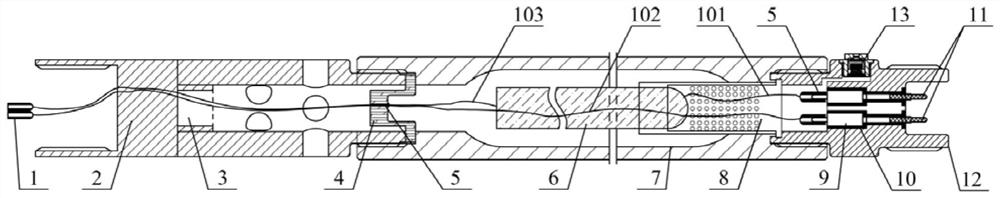
[0025] Such as figure 1 shown. CO 2 The built-in circuit structure of the cracker includes electrode socket 1, release head 2, tension type rupture disc 4, high-pressure self-tightening sealing structure 5, heater 6, liquid storage tube 7, screen tube 8, electrode 9, rubber sleeve 10, An electrode plug 11, an inflatable head 12 and an inflatable valve 13 inside the inflatable head.

[0026] The electrode 9 is wrapped with a rubber sleeve 10 and placed inside the inflatable head 12, and a high-pressure self-tightening sealing structure 5 is provided at the left end of the electrode 9;

[0027] Wherein, both ends of the inflation head 12 are provided with external threads, and the left end of the inflation head 12 is additionally provided with internal threads, and the internal threads are spirally connected with the external threads at the right end of the screen pipe 8;

[0028] The wire 101 and the wire 102 are led out from the two electrodes 9 of the inflatable head 12 , ...


PUM


Abstract

The invention relates to the field of CO2 fracturing devices, in particular to a built-in circuit structure of a CO2 fracturing device. The structure comprises an electrode, a screen pipe, a wire, a high-pressure self-tightening sealing structure and a plurality of CO2 fracturing device bodies, wherein each CO2 fracturing device body comprises an inflation head, an inflation valve, a liquid storage pipe, a tension type rupture disk, a release head and a heater; the heater is arranged in the screen pipe; the inflation head, the screen pipe and the heater are connected and then integrally placed in the liquid storage pipe, two electrodes are arranged in the inflation head, electrode plugs are fixed to the right ends of the two electrodes, a wire led out of the electrode is connected with the heater, and the connected wire penetrates through a tensioning type rupture disk with a reserved threading hole, is led out of the pipe through a release head with a threading hole, and is connected with a socket, so that it is conveniently connected with a plug of an electrode of the inflation head of the next CO2 fracturing device during construction. The built-in circuit structure adopted by the invention realizes stable transmission of a circuit connected in series with the CO2 fracturing devices and long-distance implementation of a CO2 fracturing technology.

Description

technical field [0001] The present invention relates to CO 2 The field of cracking devices, especially a kind of CO 2 The cracker has a built-in circuit structure. Background technique [0002] my country is the largest producer and consumer of raw coal in the world, and it is also a country where various mine disasters frequently occur. Among all kinds of coal mine disasters, gas disasters are particularly serious, causing huge economic losses and bad social impact. At the same time, coal bed methane (coal bed methane) is also a clean energy source with broad prospects for development and application. [0003] CO 2 Fracturing is a new type of coal mine gas control technology, which releases energy to crack the coal body through the phase transition of carbon dioxide, which has the advantages of safety, high efficiency, and no pollution. When the fracturing coal body is drilled deep, multiple CO 2 Only when the cracker is connected can the impact range be wider, the ef...

Claims


Application Information

Patent Timeline
Patent Type & Authority Applications(China)
IPC IPC(8): F42B3/04F42D1/045
CPCF42B3/04F42D1/045
Inventor 曹运兴张新生张军胜郭帅房杨百舸田林石玢曹雍星
Owner HENAN POLYTECHNIC UNIV
Why Eureka
Try Eureka