
Construction method for machining special-shaped steel component through positioning frame

A construction method and positioning frame technology, applied in metal processing machinery parts, positioning devices, metal processing, etc., can solve the problems of difficult positioning, large angle deviation, and low precision, so as to reduce engineering costs, save labor costs, and speed up construction The effect of progress

Active Publication Date: 2021-10-19
中铁建设集团中南建设有限公司 +1
View PDF9 Cites 0 Cited by
  • Summary
  • Abstract
  • Description
  • Claims
  • Application Information

AI Technical Summary

Problems solved by technology

[0002] High-rise buildings refer to multi-storey buildings exceeding a certain height and number of floors. With the gradual increase in the application of steel structures in high-rise buildings, the use of steel components such as special-shaped steel columns has also gradually increased, but it is difficult to locate them during processing. Angle Large deviation, low precision and other problems, based on this, this application proposes a construction method using positioning frame to process special-shaped steel components

Method used


Image

  • Construction method for machining special-shaped steel component through positioning frame

Examples


Embodiment 1

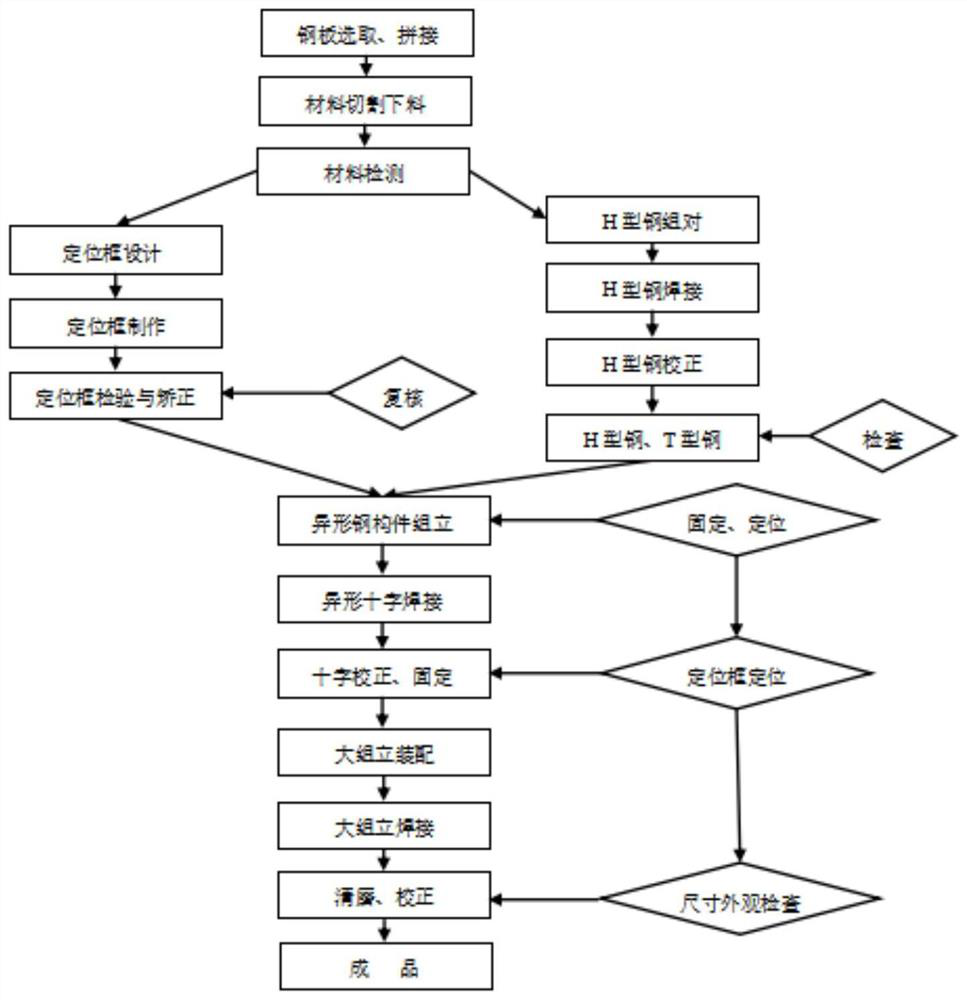
[0028] see figure 1 , a construction method for processing special-shaped steel members using a positioning frame, comprising the following steps:

[0029] Step 1. Steel plate splicing. The operator should mark the steel plate according to the requirements of the splicing diagram, then cut and splice the steel plate, and polish the splicing joint groove surface and the range of 20mm on both sides of the groove. No oil, rust and other dirt;

[0030] Step 2. Cutting and blanking of the main material. Use a straight strip cutting machine to vertically blank both sides of the wing plate and web of the section steel member at the same time, and check the first piece. After the blanking is completed, the construction personnel should transplant the furnace batch number according to the material , mark the project name, steel plate specification, and part number on the parts after blanking, and store them in categories;

[0031] Step 3. Assembling the H-shaped steel, use a semi-aut...

Embodiment 2

[0048] see figure 1 , a construction method for processing special-shaped steel members using a positioning frame, comprising the following steps:

[0049] Step 1. Steel plate splicing. The operator should mark the steel plate according to the requirements of the splicing diagram, then cut and splice the steel plate, and polish the splicing joint groove surface and the range of 20mm on both sides of the groove. No oil, rust and other dirt;

[0050] Step 2. Cutting and blanking of the main material. Use a straight strip cutting machine to vertically blank both sides of the wing plate and web of the section steel member at the same time, and check the first piece. After the blanking is completed, the construction personnel should transplant the furnace batch number according to the material , mark the project name, steel plate specification, and part number on the parts after blanking, and store them in categories;

[0051] Step 3. Assembling the H-shaped steel, use a semi-aut...


PUM

PropertyMeasurementUnit
thicknessaaaaaaaaaa
lengthaaaaaaaaaa
lengthaaaaaaaaaa

Abstract

The invention discloses a construction method for machining a special-shaped steel component through a positioning frame. The construction method comprises the steps of steel plate splicing, main material cutting and discharging, H-shaped steel assembling, T-shaped steel assembling, H-shaped steel and T-shaped steel welding seam welding, H-shaped steel correction, T-shaped steel segmentation, special-shaped cross-shaped steel column assembling, special-shaped cross-shaped steel column correction, large-assembly assembling, large-assembly welding, cleaning and grinding and correction. The construction method has the advantage that the construction progress is accelerated. Compared with a traditional lofting splicing construction method, one-time machining forming can be guaranteed; and the engineering cost is reduced. Compared with the traditional lofting splicing construction method (the first-pass yield is lower than 70%), the one-time forming rate is increased, and the labor cost is saved by 30%; and the engineering quality is improved. The positioning frame is adopted to control the assembly precision and welding deformation of the special-shaped steel members, and the pass yield reaches 100%.

Description

technical field [0001] The invention relates to a construction method of a special-shaped steel component, in particular to a construction method for processing a special-shaped steel component by using a positioning frame, and belongs to the technical field of high-rise building construction. Background technique [0002] High-rise buildings refer to multi-storey buildings exceeding a certain height and number of floors. With the gradual increase in the application of steel structures in high-rise buildings, the use of steel components such as special-shaped steel columns has also gradually increased. However, it is difficult to locate them during processing, and the angle Large deviation, low precision and other problems, based on this, this application proposes a construction method of processing special-shaped steel components using positioning frames. Contents of the invention [0003] The object of the present invention is to provide a construction method for process...

Claims


Application Information

Patent Timeline
Patent Type & Authority Applications(China)
IPC IPC(8): B23P15/00B23Q3/06B23Q7/00
CPCB23P15/00B23Q3/06B23Q7/00
Inventor 张雷余爱民迟长哲江张宿郭磊田亮畅继鹏邱锐夏钊
Owner 中铁建设集团中南建设有限公司
Learn More