
Mouth-holding nozzle structure of atomization inhaler

A technology of atomizing inhaler and tube structure, which is applied in the field of medical equipment, can solve the problems of easy fatigue, affecting the effect of atomizing inhalation, and the inability of patients to inhale medicine independently, so as to improve the curative effect of atomizing inhalation, increase the sense of touch, increase the The effect of dilatation

Pending Publication Date: 2021-10-15
成都市中西医结合医院
View PDF1 Cites 0 Cited by
  • Summary
  • Abstract
  • Description
  • Claims
  • Application Information

AI Technical Summary

Problems solved by technology

When the patient is anesthetized and undergoing surgery, the endotracheal tube is inserted into the respiratory tract, the atomization driving device is turned on, the compressor works, the air is compressed, and the medicine in the medicine tank is pressed to the atomization plug, and the medicine is atomized. The drug enters the respiratory tract through the tracheal tube to solve the problem that the patient cannot take the drug independently during the operation
[0004] There is no groove in the mouth of the existing nebulizer inhaler, and patients with the occlusal mouth need to hold the nebulizer, and at the same time shrink the mouth of the machine mouth to ensure its airtightness and prevent the mist from leaking out. When the patient keeps the wheel machine contracted for a long time, the state of occlusal force is easy to cause fatigue, which affects the effect of atomization inhalation

Method used


Image

  • Mouth-holding nozzle structure of atomization inhaler
  • Mouth-holding nozzle structure of atomization inhaler
  • Mouth-holding nozzle structure of atomization inhaler

Examples


Embodiment

[0036] as attached figure 1 to attach Figure 9 Shown:

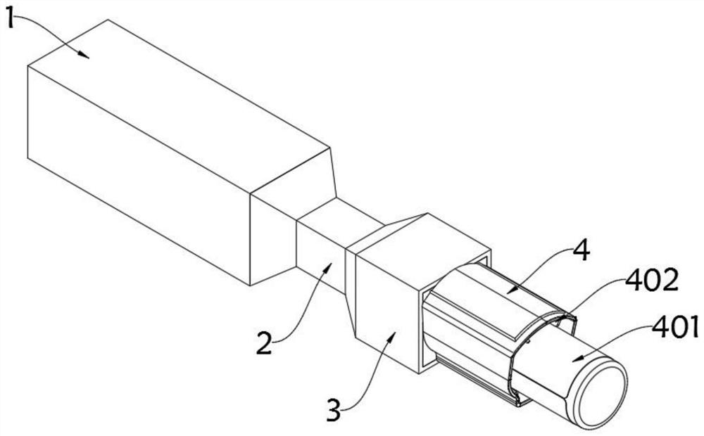
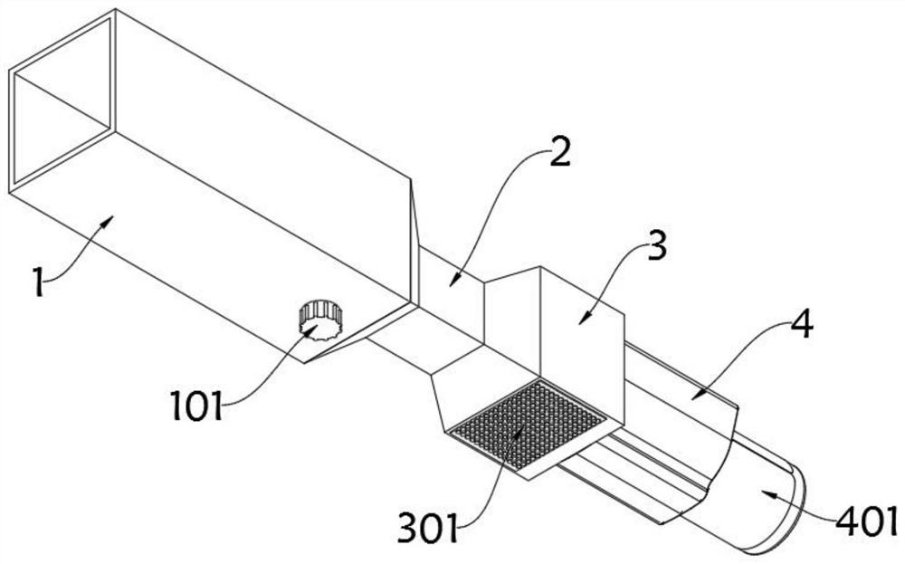
[0037] The invention provides a mouthpiece structure of an atomized inhaler, which includes a mouthpiece front tube 1; the mouthpiece front tube 1 is a square tube structure, and the rear end of the mouthpiece front tube 1 is butted with a occlusal mouthpiece 2; The mouth tube 2 is a structure with wide left and right ends and a narrow middle. The other end of the bite mouth tube 2 is fixedly connected with the inner mouth tube 3. figure 2 It can be seen that the inner mouth tube 3 includes an anti-skid touch plate 301, and the bottom plane of the inner mouth tube 3 is fixedly equipped with an anti-skid touch plate 301. The contact position can make the inner mouth tube 3 fit together, increase the tactile feeling, and avoid falling out of the mouth; the inner mouth tube 3 is a square tube structure, and the other end of the inner mouth tube 3 is docked with the inner extension tube 4;

[0038] The end of the inner e...


PUM


Abstract

The invention provides a mouth-holding nozzle structure of an atomization inhaler, relates to the technical field of medical instruments, and aims to solve the problems that a mouth-holding mouth of an existing aerosol inhaler is not provided with a groove, a patient with an occlusion mouth needs to hold an atomizer and contract the mouth-holding mouth of a turn machine so as to ensure the leakproofness of the mouth-holding mouth and prevent mist leakage, and when the aerosol inhalation amount is large, the patient keeps the turn machine to contract for a long time, the aerosol inhalation effect is affected due to the fact that a user easily feels fatigue when holding the aerosol inhalation device up and down in an occlusion force state. The mouth-holding nozzle structure comprises a mouth holding front pipe. The mouth holding front pipe is of a square pipe structure, and the rear end of the mouth holding front pipe is in butt joint with an occlusion mouth pipe; the occlusion opening pipe is of a structure with the left end and the right end wide and the middle narrow, and the other end of the occlusion opening pipe is fixedly in butt joint with the internal opening pipe; the inner opening pipe is of a square pipe structure, and the other end of the inner opening pipe is in butt joint with an inner extending pipe. On the original basis, the caliber is enlarged, the expansion degree of the throat is increased, liquid medicine can enter the respiratory tract more effectively, and atomization ventilation is improved.

Description

technical field [0001] The invention relates to the technical field of medical devices, and more specifically relates to a mouth-in-mouth structure of an atomized inhaler. Background technique [0002] Nebulization therapy mainly refers to aerosol inhalation therapy, and nebulization inhalers are usually required in the process of surgical treatment of anesthetic inhalation and lung disease treatment. [0003] For example, in patent application number CN201911190746.2, an aerosol inhaler for anesthesia includes a tracheal catheter, an adapter, a ventilation tube, and an atomization drive device; the adapter includes an L-shaped joint and a Y-shaped joint, and one end of the L-shaped joint is connected to the trachea Conduit connection, the other end is connected to a nozzle of the Y-shaped connector, and the two nozzles at the other end of the Y-shaped connector are connected to a ventilator, one of which is connected to the oxygen supply device; the top of the L-shaped conn...

Claims


Application Information

Patent Timeline
Patent Type & Authority Applications(China)
IPC IPC(8): A61M15/00A61M11/00
CPCA61M11/00A61M15/0021A61M15/0001
Inventor 袁惠罗慧敏白静蓉
Owner 成都市中西医结合医院
Learn More