
Flip light-emitting diode chip and preparation method thereof

A technology for light-emitting diodes and chips, applied in electrical components, circuits, semiconductor devices, etc., can solve the problems of Bragg mirror exposure, affecting the luminous efficiency of flip-chip light-emitting diode chips, affecting the quality of Bragg mirrors, etc., to ensure luminous efficiency and Reliability, quality of protection, good effect of surface quality

Active Publication Date: 2021-10-08
HC SEMITEK ZHEJIANG CO LTD
View PDF5 Cites 2 Cited by
  • Summary
  • Abstract
  • Description
  • Claims
  • Application Information

AI Technical Summary

Problems solved by technology

[0004] When preparing the first through holes corresponding to the n-electrode and the p-electrode on the insulating protective layer, the first through-hole and the second through-hole are usually directly etched on the insulating protective layer, but the first through-hole and the second through-hole The Bragg reflector that the hole passes through will expose part of the Bragg reflector, so that the subsequent preparation steps of the epitaxial wafer may affect the quality of the Bragg reflector, thereby affecting the light output of the Bragg reflector and affecting the luminous efficiency of the flip-chip LED chip

Method used


Image

  • Flip light-emitting diode chip and preparation method thereof
  • Flip light-emitting diode chip and preparation method thereof
  • Flip light-emitting diode chip and preparation method thereof

Examples


Embodiment Construction

[0035] In order to make the objects, technical solutions, and advantages of the present invention, the present disclosure will be further described in detail below with reference to the accompanying drawings.

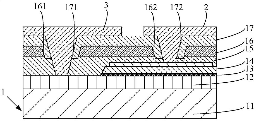
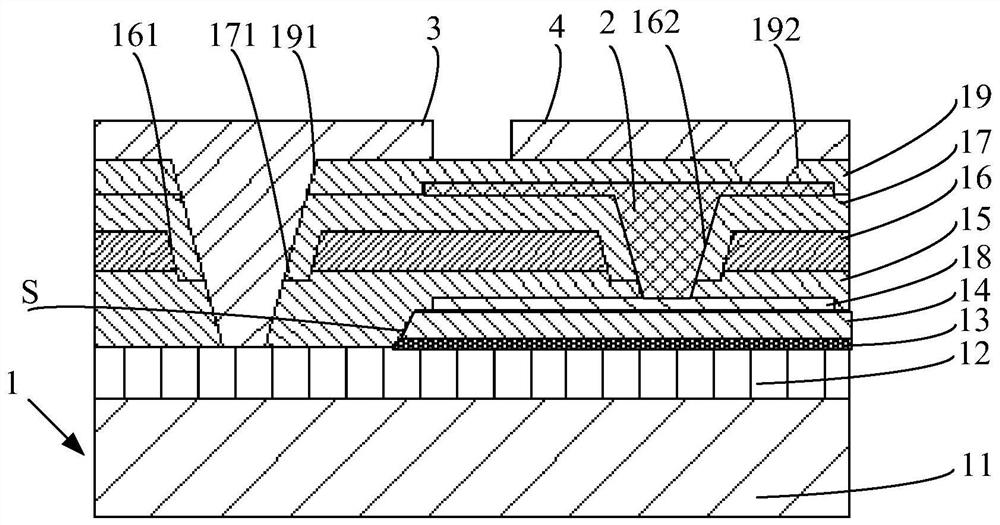
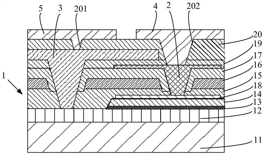
[0036] figure 1 It is a schematic structural diagram of a flip-loaded light-emitting diode chip provided by the embodiment of the present disclosure, such as figure 1 Design, the present disclosure provides a flip-loaded light-emitting diode chip, and the light-emitting diode chip includes an epitaxial sheet 1, the primary P electrode 2 and the primary N electrode 3, and the epitaxial sheet 1 includes a substrate 11 and sequentially laminated in a substrate 11. The upper N-type layer 12, the light-emitting layer 13, the p-type layer 14, the corrosion cutoff layer 15, the Prague mirror 16 and the first insulating protective layer 17.

[0037] The surface of the Prague mirror 16 has a spaced first receiving groove 161 and a second receiving groove 162, and the first receivin...


PUM

PropertyMeasurementUnit
thicknessaaaaaaaaaa

Abstract

The invention discloses a flip light-emitting diode chip and a preparation method thereof, and belongs to the field of light-emitting diode manufacturing. A corrosion cut-off layer is added between a p-type layer and a Bragg reflector, and a first accommodating groove and a second accommodating groove extend to the corrosion cut-off layer. The addition of the corrosion cut-off layer prevents the formation of the first accommodating groove and the second accommodating groove on the Bragg reflector from affecting the p-type layer, and ensures the surface quality of the p-type layer. The first accommodating groove and the second accommodating groove provide a covering space for the first insulating protection layer, and wrap a part of the Bragg reflector in the first insulating protection layer for protection, and then a first through hole and a second through hole are formed in the surface of the first insulating protection layer. When the first through hole and the second through hole are formed, the Bragg reflector covered by the first insulation protection layer is not affected, the quality of the Bragg reflector is effectively protected, and light emitting of the Bragg reflector and the light emitting efficiency of the flip light-emitting diode chip are guaranteed.

Description

Technical field [0001] The present invention relates to the field of light emitting diode, and more particularly to flip-loaded light-emitting diode chips and preparation methods thereof. Background technique [0002] LED is a semiconductor electronic component capable of illuminating. As an efficient, environmentally friendly, green new solid-state lighting source, it is rapidly available, such as traffic signals, automotive inside and outside lights, urban landscape lighting, mobile backlight, etc., improving epitaxial luminous efficiency is the target of luminous diodes constantly pursue . Flip LED is one of the light emitting diodes. [0003] The flip light-emitting diode chip is an infrastructure for preparing inverted light-emitting diodes. The flip light-emitting diode chip includes an epitaxial sheet, a P electrode and an N electrode, and the epitaxial sheet comprises a substrate and sequentially laminated a n-type layer on a substrate, luminous Layers, P-type layers, Pra...

Claims


Application Information

Patent Timeline
Patent Type & Authority Applications(China)
IPC IPC(8): H01L33/46H01L33/44H01L33/00
CPCH01L33/46H01L33/44H01L33/0075H01L2933/0025
Inventor 张威黄磊连程杰王佳吴志浩李鹏
Owner HC SEMITEK ZHEJIANG CO LTD
Learn More