
Cold and hot impact test method for electronic structural member and test equipment

A technology of thermal shock testing and electronic structure, applied in the direction of measuring electricity, measuring devices, measuring electrical variables, etc., can solve the problems of aggravating material fatigue, fatigue resistance performance testing, and low accuracy of test performance data, so as to prevent high and low temperature Influence of the environment, the effect of ensuring the circuit connection

Active Publication Date: 2021-10-08
深圳市优瑞特检测技术有限公司
View PDF13 Cites 5 Cited by
  • Summary
  • Abstract
  • Description
  • Claims
  • Application Information

AI Technical Summary

Problems solved by technology

The utility model enlarges the temperature sudden change range of the temperature sensor through the high-temperature furnace and the air cooler, and increases the temperature change rate, thereby aggravating the material fatigue caused by the cold and heat impact, and increasing the number of tests per unit time through the driving mechanism, so as to shorten "Test cycle", but when the device conducts the thermal shock test, it only tests the fatigue resistance performance of the electronic structural parts material, and fails to detect whether the electronic structural parts continue to operate normally, resulting in relatively limited test results;
[0005] 2. The comparative document CN108469393A discloses a thermal shock test equipment, "comprising: a heating device and a cooling device, the heating device and the cooling device are connected through a pipeline, and the two ends of the pipeline extend to the inside of the heating device and the cooling device respectively, The pipeline is provided with a valve body to control its on-off, and a loading cylinder is slidably arranged inside the pipeline, and the loading cylinder is connected with a conveying mechanism that drives it to move back and forth to the heating device or the cooling device The cold and hot shock test equipment with the above structure uses pipelines to transport the loading cylinder for placing workpieces, and the connection between the heating device and the cooling device is cut off through the valve body, the cold and hot conversion process and the impact recovery time are short, and the test equipment is small in size and low in cost. , high energy utilization efficiency, and easy operation, thus providing a very cost-effective test equipment for small workpieces that need to be subjected to thermal shock tests.” However, the device failed to withstand heat during thermal shock tests During the test, the heat resistance performance of electronic structural parts was tested, resulting in incomplete test results;
It realizes fast switching between different temperature boundary conditions, and can accurately measure the opening and closing rate and changes of the thermostat", but the range of cold and heat shock inside the device's cold and heat shock chamber cannot realize multi-range switching, resulting in The thermal and thermal shock test range of the device is not comprehensive enough, and the data accuracy of the test performance is low

Method used


Image

  • Cold and hot impact test method for electronic structural member and test equipment
  • Cold and hot impact test method for electronic structural member and test equipment
  • Cold and hot impact test method for electronic structural member and test equipment

Examples


Embodiment Construction

[0041] The following will clearly and completely describe the technical solutions in the embodiments of the present invention with reference to the accompanying drawings in the embodiments of the present invention. Obviously, the described embodiments are only some, not all, embodiments of the present invention. Based on the embodiments of the present invention, all other embodiments obtained by persons of ordinary skill in the art without making creative efforts belong to the protection scope of the present invention.

[0042] In the description of the present invention, it should be noted that the terms "upper", "lower", "inner", "outer", "front end", "rear end", "both ends", "one end", "another end" The orientation or positional relationship indicated by etc. is based on the orientation or positional relationship shown in the drawings, and is only for the convenience of describing the present invention and simplifying the description, rather than indicating or implying that ...


PUM


Abstract

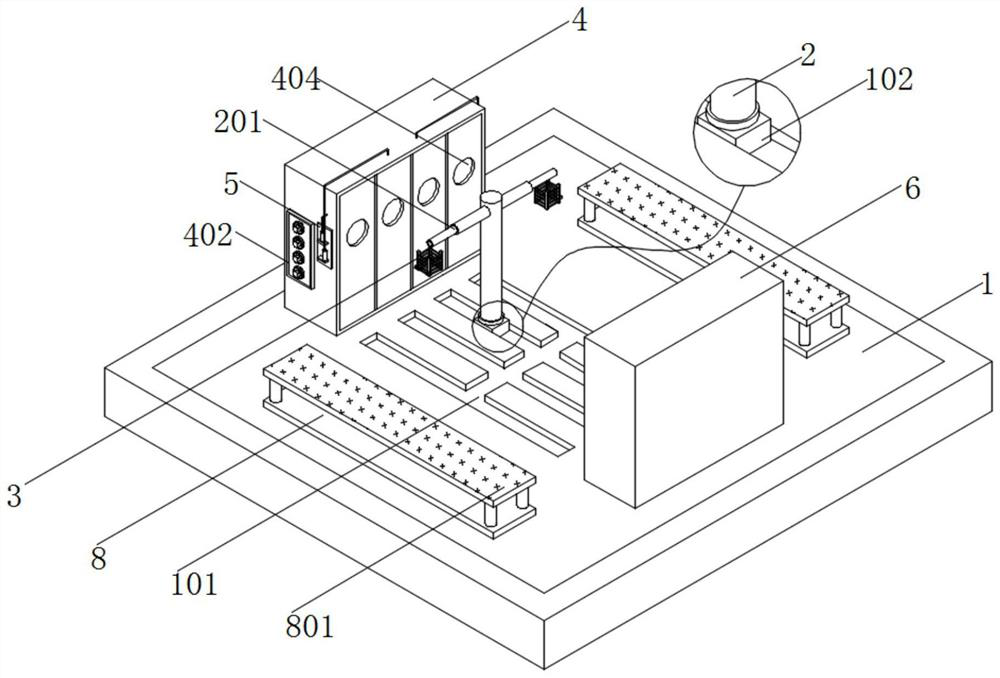
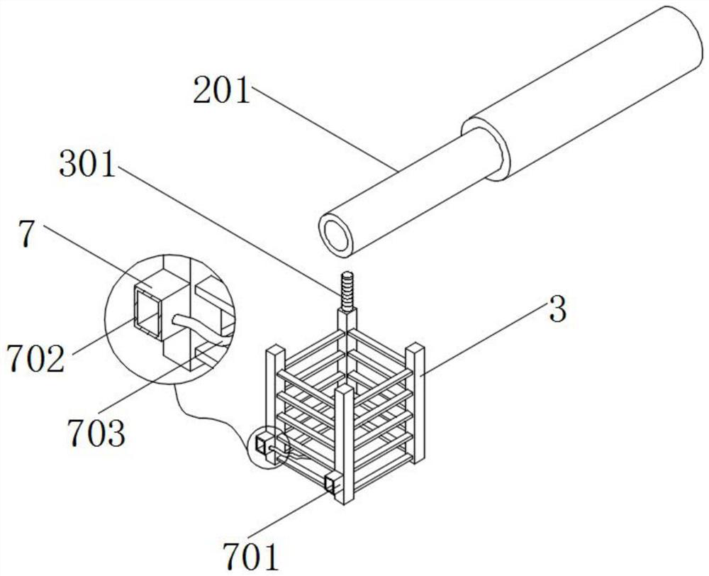
The invention discloses a cold and hot impact test method for an electronic structural member and test equipment, the test equipment comprises a base plate and a first test box, the top of the base plate is provided with a combined chute, the interior of the combined chute is slidably connected with a sliding block, the top of the sliding block is provided with a turntable, the top of the turntable is provided with a vertical rod, the surface of the vertical rod is provided with two groups of symmetrically arranged electric telescopic rods, the tail ends of the electric telescopic rods are in threaded connection with threaded rods, the bottoms of the threaded rods are provided with a placement frame, and the surface, away from the electric telescopic rods, of the placement frame is provided with a first test box and a second test box which are symmetrically arranged. According to the invention, the first test box and the second test box are arranged to detect and analyze the specific condition of the performance of the electronic structural member when the electronic structural member is subjected to a cold and hot impact test, and the detection plate and the reagent bottle are arranged to observe the color change condition of a solution in the reagent bottle and the precipitation generation condition, and whether the material performance of the electronic structural member is good or not can be judged.

Description

technical field [0001] The invention relates to the technical field of thermal shock testing, in particular to a thermal shock testing method and testing equipment for electronic structural parts. Background technique [0002] In the process of rapid temperature changes, the damage to the product due to thermal expansion and contraction or other reasons is detected. This test is called thermal shock test. Through the thermal shock test, the electronic structural parts can be tested for sharp changes in the ambient temperature. It can be used to test the adaptability of electronic structural parts in the engineering development stage, and it can be used to find the design and process defects of electronic structural parts products, and it has important experimental significance for improving the electronic structural parts products and performance in the later stage. [0003] The defects of existing hot and cold shock testing equipment are: [0004] 1. The comparative docume...

Claims


Application Information

Patent Timeline
Patent Type & Authority Applications(China)
IPC IPC(8): G01R31/00
CPCG01R31/00
Inventor 熊艳慧梅礼光陈勇李胜
Owner 深圳市优瑞特检测技术有限公司
Learn More