
Flexible coupling mechanism and displacement sensing device with same

A coupling mechanism and sensing device technology, applied in the detection field, can solve the problems of difficult control of injection molding size, high cost, and affecting the accuracy of sensor output signals, etc., and achieve the effect of simple and easy control of the molding process and low cost

Active Publication Date: 2021-10-08
CONTINENTAL AUTOMOTIVE CORP LIANYUNGANG CO LTD
View PDF17 Cites 1 Cited by
  • Summary
  • Abstract
  • Description
  • Claims
  • Application Information

AI Technical Summary

Problems solved by technology

But the current ball hinge design, there are still some shortcomings
The ball head is pressed into the connecting rod, which requires the connecting rod to be injection molded with TPC (ThermoPlastic Composites, thermoplastic-based composite material) soft rubber with high elasticity, and the cost is relatively high; grease lubrication is required between the spherical seat and the ball head; the spherical seat of the connecting rod Therefore, it is difficult to control the injection molding size and the cost of the mold is high; the connecting rod is made of TPC soft rubber, which leads to low rigidity of the connecting rod and affects the accuracy of the sensor output signal

Method used


Image

  • Flexible coupling mechanism and displacement sensing device with same
  • Flexible coupling mechanism and displacement sensing device with same
  • Flexible coupling mechanism and displacement sensing device with same

Examples


Embodiment Construction

[0028] The scheme of the present invention will be further described below in conjunction with the accompanying drawings and preferred embodiments.

[0029] In the following description, numerous specific details are set forth in order to enable those skilled in the art to fully understand the present invention. It will be apparent, however, to one skilled in the art that the present invention may be practiced without some of these specific details. Furthermore, it should be understood that the invention is not limited to the particular embodiments described. Instead, it is conceivable to implement the present invention in any combination of the following features and elements, regardless of whether they relate to different embodiments. Accordingly, the following aspects, features, embodiments and advantages are by way of illustration only and should not be considered elements or limitations of the claims unless explicitly stated in the claims. In addition, if words indicati...


PUM


Abstract

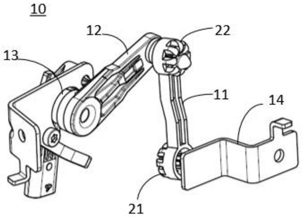
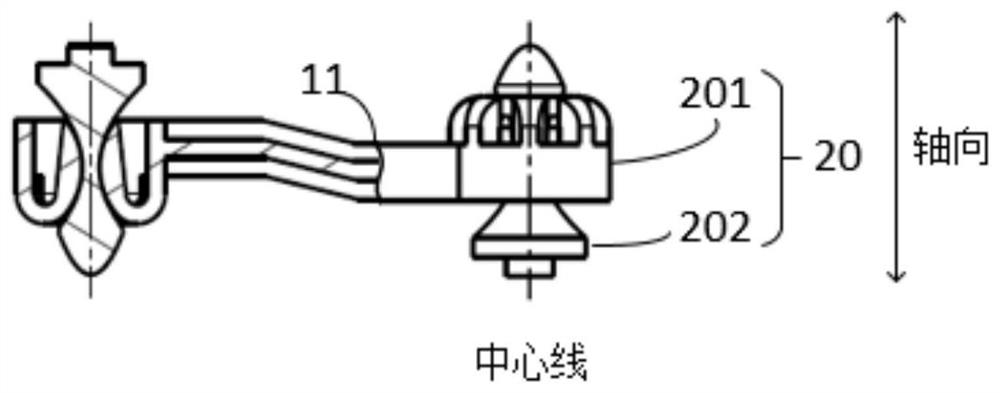
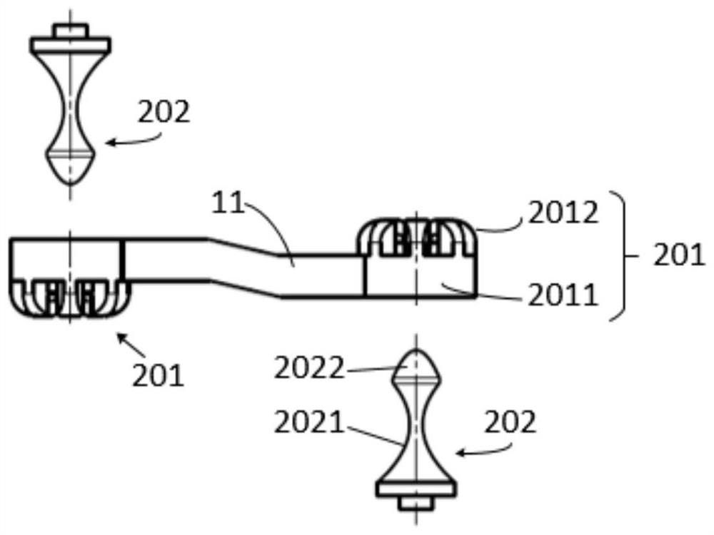
The invention provides a flexible coupling mechanism and a displacement sensing device with the same. The flexible coupling mechanism comprises a flexible bearing part and a connecting shaft inserted into the flexible bearing part. The flexible bearing part comprises a clamping jaw part, the clamping jaw part is composed of a plurality of clamping jaws, each clamping jaw comprises a fixed end and a free end, the free ends of the clamping jaws jointly define a channel allowing the connecting shaft to penetrate through, and the channel is used for supporting and limiting the connecting shaft. The displacement sensing device comprises a connecting rod, a swing arm and an angle sensor. One end of the connecting rod is connected with a tested assembly through the flexible coupling mechanism, the other end of the connecting rod is connected with one end of the swing arm through the flexible coupling mechanism, and the other end of the swing arm is connected to the angle sensor. The flexible coupling mechanism and the displacement sensing device have the advantages of being low in cost, easy to machine, easy to form, high in strength and capable of achieving self-lubrication.

Description

technical field [0001] The invention belongs to the detection technical field, and in particular relates to a flexible coupling mechanism for detecting the displacement of motor vehicle components and a displacement sensing device with the mechanism. Background technique [0002] A known displacement sensing device for detecting displacement of components of a motor vehicle includes an angle sensor articulated through a swing arm and a hinge mechanism at one end of a connecting rod, the other end of which is also connected to a component of the motor vehicle. The component is, for example, a motor vehicle chassis control arm or the like. Usually, the swing arm is connected to the connecting rod by means of a joint, for example with a ball joint fastened to the swing arm and a spherical seat fastened to the connecting rod. The linkage converts a linear movement up and down of a component of the motor vehicle, for example a chassis control arm, into a rotational movement on t...

Claims


Application Information

Patent Timeline
Patent Type & Authority Applications(China)
IPC IPC(8): G01B21/02G01B21/22
CPCG01B21/02G01B21/22F16C11/0614F16C11/08F16C11/0685F16C2226/74F16C2326/05F16C11/12B60G2204/116B60G2204/416B60G7/005F16C11/0604F16C11/0657
Inventor 蔡国震
Owner CONTINENTAL AUTOMOTIVE CORP LIANYUNGANG CO LTD
Learn More