Blind estimation method for code element rate and code element conversion time of digital modulation signal

A technology of signal symbol and digital modulation, applied in data rate detection devices, digital transmission systems, electrical components, etc., can solve the problems of sampling clock jitter, drift sensitivity, and low signal-to-noise ratio of monitoring signals, and achieve good estimation results. Highly robust and adaptable effects

Active Publication Date: 2021-10-01
10TH RES INST OF CETC
View PDF6 Cites 2 Cited by
  • Summary
  • Abstract
  • Description
  • Claims
  • Application Information

AI Technical Summary

Problems solved by technology

[0006] First, lack of applicability and stability
The existing technology can only be effective for certain types of digital modulation signals, and the parameters required by the algorithm need to be adjusted according to the range of signal characteristics, and it is sensitive to carrier offset, sampling clock jitter, and drift
[0007] Second, the anti-noise performance is insufficient
For radio monitoring equipment, the signal parameters are almost completely blind. Due to the influence of channel noise, multipath, etc., the signal-to-noise ratio of the monitoring signal is low. It is difficult for existing methods to eliminate the influence of noise and other interference by accumulating long-sequence signal energy.

Method used


Image

  • Blind estimation method for code element rate and code element conversion time of digital modulation signal
  • Blind estimation method for code element rate and code element conversion time of digital modulation signal
  • Blind estimation method for code element rate and code element conversion time of digital modulation signal

Examples


Embodiment Construction

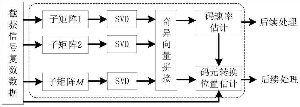
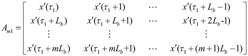
[0017] refer to figure 1. According to the present invention, at first, the complex data of the signal is intercepted at the sampling time t, and the signal data after analog / digital (A / D) sampling is converted into a complex signal form, and the Hankel data matrix of M * N is constructed, and the matrix adjacent column vector Delay one sampling moment, and secondly, divide the M×N-dimensional Hankel data matrix into several M q ×N(M 1 +M 2 +M 3 +…+M Q )=M sub-matrix, and carry out singular value decomposition SVD to each sub-matrix, obtain the sub-envelope of the first, second, and third left singular vectors of the sub-matrix, splice the singular vectors according to the order of the sub-matrix, and obtain the first, second, and third left singular vector envelopes; then fast Fourier transform (FFT) is performed on the first, second, and third left singular vector envelopes, and the spectra of the obtained three singular vector envelopes are added to detect the three fr...


PUM


Abstract

The blind estimation method for the code element rate and the code element conversion time of the digital modulation signal, disclosed by the invention, is high in applicability, high in robustness and high in anti-noise capability. According to the technical scheme, the method comprises the following steps of: firstly, constructing data in an observation time length into an M*N Hankel data matrix, and performing singular value decomposition on the matrix after partitioning the matrix; then, taking a first left singular vector envelope, a second left singular vector envelope and a third left singular vector envelope, carrying out FFT, adding frequency spectrums of the three obtained singular vector envelopes, and detecting a frequency corresponding to a maximum spectrum value of the sum of the three frequency spectrums at a non-zero frequency as a code element rate; then, generating detection pulses according to the estimated code element rate, calculating the dot product sum of the detection pulses with different delay amounts and the second singular vector envelope subjected to smoothing filtering, and selecting a correct code element conversion time by utilizing the singular value capability distribution difference between a code element truncation data matrix and other forms of data matrixes with the same dimension, and obtaining the optimal sampling time by delaying the sampling point of the chip by one half at the code element conversion time.

Description

technical field [0001] The present invention belongs to the category of digital modulation signal parameter estimation, and mainly relates to a digital modulation signal symbol rate and symbol conversion time (best sampling time) based on singular value decomposition (Singular value decomposition, SVD) suitable for single-channel received data Estimation method. Background technique [0002] In recent years, with the continuous development of radio technology and the rapid advancement of modern communication and signal processing technology, radio signal systems and modulation styles have become increasingly complex and diverse, and increasingly complex and diverse radio signals have gradually penetrated into every corner. In addition, the environment of signal transmission is becoming more and more harsh. All these changes make the estimation of wireless signal parameters more demanding and more difficult. It is difficult to balance the accuracy of parameter estimation and...

Claims


Application Information

Patent Timeline
IPC IPC(8): H04L1/00H04L25/02
CPCH04L1/0038H04L25/0262Y02D30/70
Inventor 戚连刚陈颖吴明钦潘灵郝黎宏张昊
Owner 10TH RES INST OF CETC
Why Eureka
Try Eureka