Environment-friendly heat insulation plastic film processing device
A technology for a plastic film and a processing device, which is applied in the field of environmentally friendly heat-insulating plastic film processing devices, can solve problems such as inconvenient feeding, and achieve the effects of increasing maintenance costs, facilitating batch feeding, and facilitating feeding.
- Summary
- Abstract
- Description
- Claims
- Application Information
AI Technical Summary
Problems solved by technology
Method used
Image
Examples
Embodiment 1
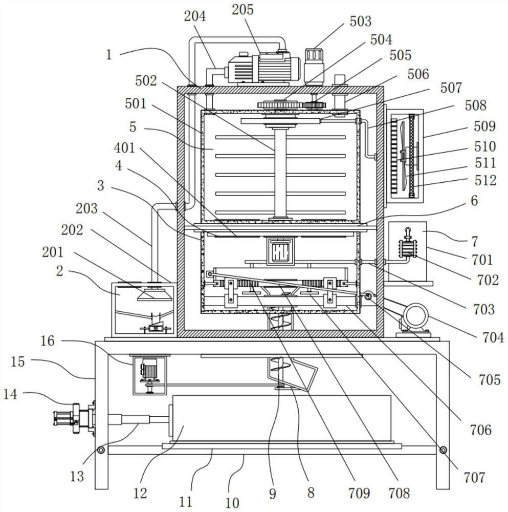
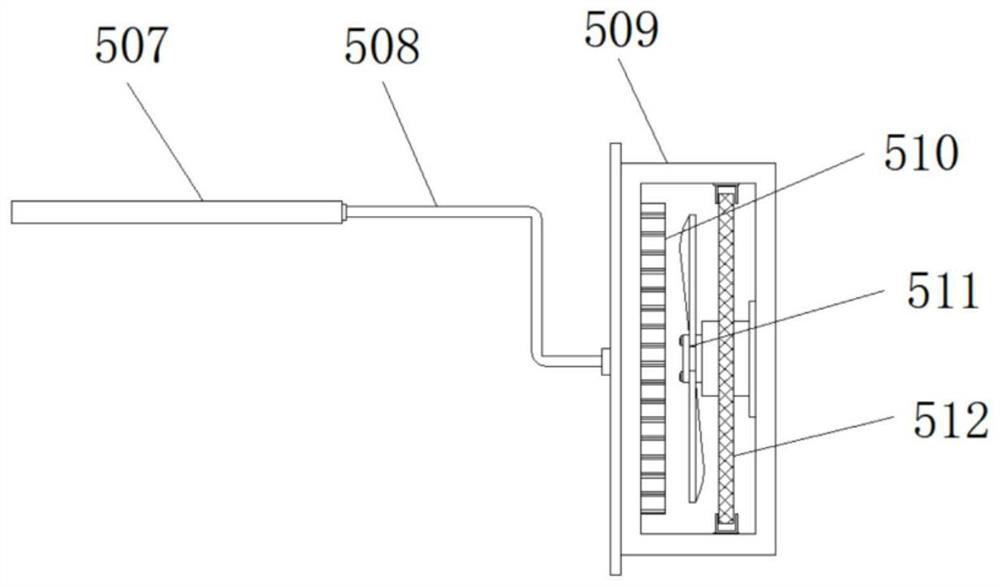
[0037] Example 1: See Figure 1-7 An environmentally friendly insulating plastic film processing apparatus, including the apparatus body 1 and the fixing table 15, and the bottom end of the apparatus body 1 is provided with a fixed stage 15, and the intermediate position of the device body 1 is provided with a separator 6, the separator 6. The top end is provided with a drying mechanism 5, and the bottom end of the separator 6 is provided with a screening chamber 3, and the top end of the inside of the screening chamber 3 is provided with a winding mechanism 4, and the bottom end of the screen 3 is provided with a screening-bearing mechanism 7, a device body. One side of the side is provided with a feed mechanism 2, and the bottom end of the screening chamber 3 is provided;
[0038] See Figure 1-7 An environmentally friendly insulating plastic film processing apparatus further includes an effluent mechanism including a discharge passage 8, and the discharge passage 8 is disposed be...
Embodiment 2
[0040] Example 2: The feed mechanism 2 consists of a pumping cover 201, a feed tank 202, a strip tube 203, a conductive tube 204, and a first pump 205, and the feed tank 202 is disposed on one side of the top end of the fixed stage 15. The inner portion of the feed tank 202 is provided with a sub-cover 201, and the first pump 205 is disposed on one side of the tip end of the apparatus body 1, and the model number of the first pumping pump 205 can be the input of EHS-529, the first pump 205. The pumping tube 203 is fixed between the pumping hoods 201, and the output end of the first pump 205 is provided with a conduit tube 204, the conduit tube 204 vertically penetrates the top end of the apparatus body 1 and extends to the interior of the apparatus body 1.
[0041] The pumping cover 201 is a circular stand shape, the width of the feed tank 202 and the width of the apparatus body 1 are equal;
[0042] Specifically, the first pump 205 is activated, the feed tank 202 is inhaled by th...
Embodiment 3
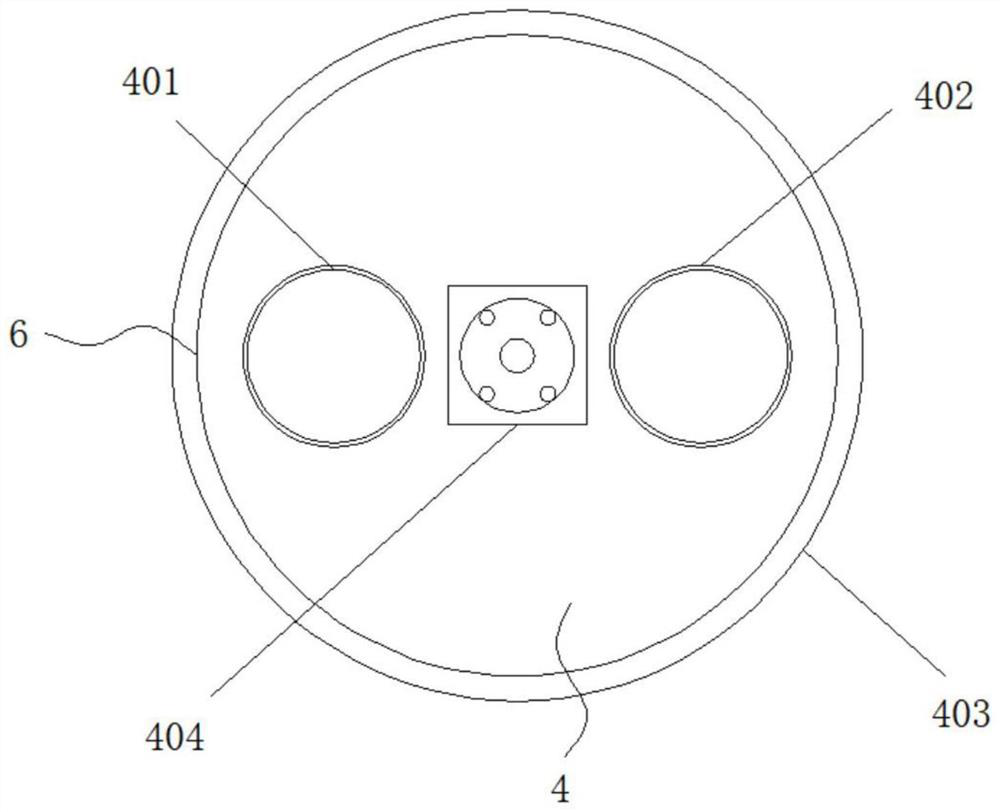
[0045] Example 3: The winding mechanism 4 consists of the first falling tank 401, the second landing groove 402, the tap plate 403, and the second drive motor 404, and the tap plate 403 is actively connected to the interior of the separator 6, the material The bottom end of the plate 403 is provided with a second drive motor 404, and the model number of the second drive motor 404 can be SJ-PXS-018-1, and the output of the second drive motor 404 is fixedly connected to the tab 403 through the coupling. One side of the inside of the tab 403 is provided with a first falling tank 401, and the other side inside the tab 403 is provided with a second falling groove 402;
[0046] The first falling tank 401 and the second landing tank 402 are circular, the first falling tank 401 and the second falling tank 402 respectively symmetrically symmetric distribution of the separator 6;
[0047] Specifically, such as figure 1 , image 3 with Figure 5 As shown, the dried particles are sealed into th...
PUM
 Abstract
Description
Claims
Application Information
 - Generate Ideas
- Intellectual Property
- Life Sciences
- Materials
- Tech Scout
- Unparalleled Data Quality
- Higher Quality Content
- 60% Fewer Hallucinations
Browse by: Latest US Patents, China's latest patents, Technical Efficacy Thesaurus, Application Domain, Technology Topic, Popular Technical Reports.
© 2025 PatSnap. All rights reserved.Legal|Privacy policy|Modern Slavery Act Transparency Statement|Sitemap|About US| Contact US: help@patsnap.com


