An electro-hydraulic composite drive system and drive method

A drive system and hydraulic technology, applied in electric braking systems, control drives, electric vehicles, etc., can solve the problems of low energy utilization rate of the whole vehicle, difficult to charge batteries with high power, low efficiency, etc., to increase additional mechanical power, The effect of improving the energy utilization rate of the whole vehicle and overcoming the driving resistance

Active Publication Date: 2022-07-29
SHANDONG UNIV OF TECH
View PDF8 Cites 0 Cited by
  • Summary
  • Abstract
  • Description
  • Claims
  • Application Information

AI Technical Summary

Problems solved by technology

However, the existing braking energy recovery scheme usually directly charges the battery. Because the braking process is usually short, it is difficult to charge the battery with high power in a short period of time. Secondly, the efficiency of the braking energy feedback process is low, because the kinetic energy is converted into electrical energy through the generator. , and then converted into chemical energy through the battery, and then converted from chemical energy into electrical energy and kinetic energy when reused, such repeated conversions lead to low energy utilization of the vehicle

Method used


Image

  • An electro-hydraulic composite drive system and drive method
  • An electro-hydraulic composite drive system and drive method
  • An electro-hydraulic composite drive system and drive method

Examples


Embodiment Construction

[0028] The technical solutions in the embodiments of the present invention will be clearly and completely described below with reference to the accompanying drawings in the embodiments of the present invention. Obviously, the described embodiments are only a part of the embodiments of the present invention, but not all of the embodiments. Based on the embodiments of the present invention, all other embodiments obtained by those of ordinary skill in the art without creative efforts shall fall within the protection scope of the present invention.

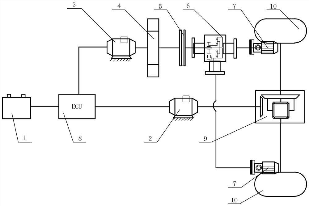
[0029] The purpose of the present invention is to provide an electro-hydraulic composite drive system and method, so as to solve the problems existing in the above-mentioned prior art, improve the braking energy recovery efficiency of pure electric vehicles, improve the energy utilization rate of the whole vehicle, and at the same time increase the additional power of the vehicle, Optimize starting and braking conditions.

[0030] In ...


PUM


Abstract

The invention discloses an electro-hydraulic composite drive system, comprising a power battery, an electric drive unit and a hydraulic drive unit. The electric drive unit includes a first motor, and the hydraulic drive unit includes a second motor, a flywheel, a clutch, an energy distribution device and a hydraulic pump / motor. The invention also provides an electro-hydraulic compound driving method, which determines the working state of the clutch according to the driving state of the vehicle. When the clutch is disengaged, the second motor can drive the flywheel to rotate and store energy; when the clutch is closed, the flywheel rotates and can utilize the energy distribution. The device drives the hydraulic pump / motor to move, and the hydraulic pump / motor drives the drive wheel to rotate; when the vehicle brakes, the power battery does not supply power, the speed of the flywheel increases, and the braking energy is recovered. The second motor outputs negative torque and outputs the same output as the first motor. The torque is coupled to act on the drive wheels. At the same time, a small part of the braking energy can be converted into electrical energy and stored in the power battery, and most of it is directly stored in the flywheel in the form of mechanical energy.

Description

technical field [0001] The invention relates to the technical field of electric vehicles and their surrounding supporting facilities, in particular to an electro-hydraulic composite drive system and a drive method. Background technique [0002] In recent years, the world is facing an energy crisis, especially the energy shortage and atmospheric pollution caused by traditional vehicles powered by petroleum energy are becoming more and more serious. Therefore, vigorously developing energy-saving and environmentally friendly new energy vehicles has gradually become a trend, and pure electric vehicles have become mainstream research. [0003] During the driving process of the car, at high speed, the hydraulic braking energy recovery system can provide higher resistance torque, good braking effect, and high energy recovery efficiency; at low speed, the braking torque provided by the hydraulic braking energy recovery system is unstable. , the energy recovery efficiency is low. ...

Claims


Application Information

Patent Timeline
Patent Type & Authority Patents(China)
IPC IPC(8): B60L15/20B60L15/32B60L7/10
CPCB60L15/20B60L15/32B60L7/10B60L2240/12B60L2240/14B60L2240/545B60L2240/423B60L2240/421Y02T10/72
Inventor 李琳张铁柱冯超鲁力群孙宾宾
Owner SHANDONG UNIV OF TECH
Why Eureka
Try Eureka