
Clamping plate of substrate cutting machine and substrate cutting method

A cutting method and cutting machine technology, applied in nonlinear optics, instruments, optics, etc., can solve problems such as splint fragments of substrate cutting machines

Pending Publication Date: 2021-09-14
SHENZHEN CHINA STAR OPTOELECTRONICS SEMICON DISPLAY TECH CO LTD
View PDF4 Cites 0 Cited by
  • Summary
  • Abstract
  • Description
  • Claims
  • Application Information

AI Technical Summary

Problems solved by technology

[0004] The embodiment of the present application provides a substrate cutting machine splint and a substrate cutting method to improve the problem that the substrate cutting machine splint will be broken when the veneer is clamped

Method used


Image

  • Clamping plate of substrate cutting machine and substrate cutting method
  • Clamping plate of substrate cutting machine and substrate cutting method
  • Clamping plate of substrate cutting machine and substrate cutting method

Examples


Embodiment Construction

[0030] The technical solutions in the embodiments of the present application will be clearly and completely described below in conjunction with the drawings in the embodiments of the present application. Apparently, the described embodiments are only some of the embodiments of this application, not all of them. Based on the embodiments in this application, all other embodiments obtained by those skilled in the art without making creative efforts belong to the scope of protection of this application.

[0031] In the description of the present application, it should be understood that the terms "center", "longitudinal", "transverse", "length", "width", "thickness", "upper", "lower", "front", " Orientation indicated by rear, left, right, vertical, horizontal, top, bottom, inside, outside, clockwise, counterclockwise, etc. The positional relationship is based on the orientation or positional relationship shown in the drawings, which is only for the convenience of describing the a...


PUM


Abstract

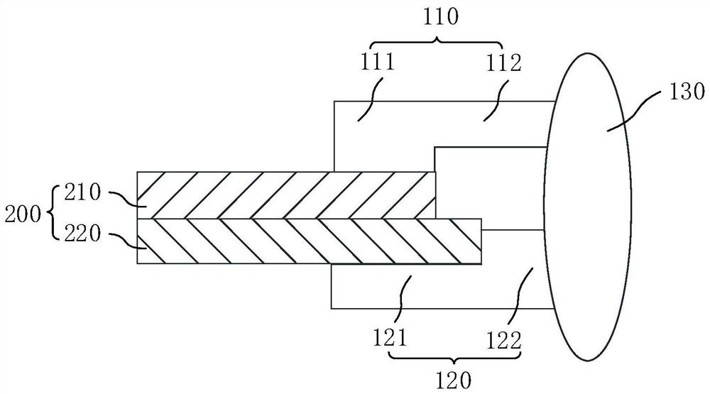
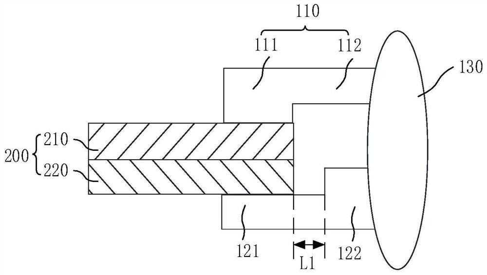
The invention discloses a clamping plate of a substrate cutting machine and a substrate cutting method. A substrate comprises a first glass plate and a second glass plate which are oppositely arranged in an attached mode, and the clamping plate of the substrate cutting machine comprises a first clamping arm, the first clamping arm comprises a first part and a second part which are sequentially arranged along the extentsion direction, and the second part is thicker than the first part; a second clamping arm comprises a third part and a fourth part which are sequentially arranged in the extending direction of the second clamping arm, the third part is thicker than the fourth part, the first part and the third part are oppositely arranged, and the second part and the fourth part are oppositely arranged; the first clamping arm is connected the second clamping arm through a connecting shaft, and the first clamping arm and the second clamping arm are arranged in a spaced mode and used for grabbing a first glass plate and a second glass plate at the same time. According to the embodiment, the second part and the third part are arranged in a staggered mode, so that the first glass plate and the second glass plate are clamped at the same time, and the problem that a clamping plate of an existing substrate cutting machine is broken during clamping is solved.

Description

technical field [0001] The application belongs to the technical field of electronic equipment, and in particular relates to a substrate cutting machine splint and a substrate cutting method. Background technique [0002] Liquid Crystal Display (LCD, Liquid Crystal Display) has many advantages such as thin body and power saving, and has been widely used. In the existing manufacturing process of liquid crystal display devices, multiple arrays are generally made on two glass substrates. The substrate and the color filter substrate, and then the two glass substrates are aligned and bonded to form a liquid crystal display motherboard, and then the liquid crystal display motherboard is cut to form a plurality of finished liquid crystal display panels. After the cutting is completed, the edges of the two glass substrates are often misaligned, but the splint of the existing substrate cutting machine will be broken when clamped. [0003] Therefore, it is necessary to conduct further...

Claims


Application Information

Patent Timeline
Patent Type & Authority Applications(China)
IPC IPC(8): G02F1/13G02F1/1333
CPCG02F1/133351G02F1/1303
Inventor 刘清林
Owner SHENZHEN CHINA STAR OPTOELECTRONICS SEMICON DISPLAY TECH CO LTD
Learn More