
Constant magnetic field immunity verification device and system

A technology of constant magnetic field and verification device, applied in the direction of measuring device, measuring device casing, measuring interference from external sources, etc., can solve the problems of inaccessible switch performance comprehensive evaluation, undetected and other problems

Active Publication Date: 2021-09-14
DEFOND ELECTECH CO LTD +1
View PDF14 Cites 0 Cited by
  • Summary
  • Abstract
  • Description
  • Claims
  • Application Information

AI Technical Summary

Problems solved by technology

[0003] In the existing technology, the test and verification of the proximity switch is only to verify the detection distance and corresponding performance of the switch under ordinary environmental conditions without a magnetic field. However, the proximity switch often needs to be applied in harsh and harsh environments such as strong magnetic field strength, and there is no such thing on the market. There is a test device for the stability and reliability of distance detection of proximity switches in harsh and harsh environments such as strong magnetic field strength, and it is impossible to further comprehensively evaluate the performance of proximity switches

Method used


Image

  • Constant magnetic field immunity verification device and system
  • Constant magnetic field immunity verification device and system
  • Constant magnetic field immunity verification device and system

Examples


Embodiment 1

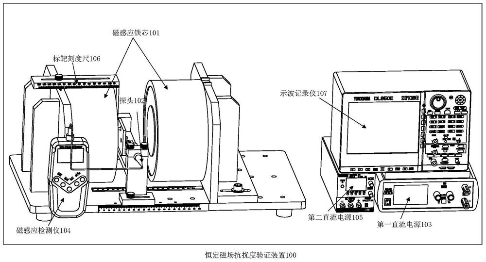
[0033] The embodiment of the present invention provides a constant magnetic field immunity verification device, see figure 1 A schematic structural diagram of a constant magnetic field immunity verification device is shown, the constant magnetic field immunity verification device 100 includes: a magnetic induction core 101, a probe 102, a first DC power supply 103, a magnetic induction detector 104, and a proximity switch (Fig. Not shown in, the position of the proximity switch is the same as the position of the probe), the second DC power supply 105, the target scale 106 and the oscilloscope 107;

[0034]The magnetic induction iron core 101 comprises an iron core induction coil, and the two ends of the iron core induction coil are respectively connected with the positive and negative poles of the first DC power supply 103, and the probe 102 is connected with the magnetic induction detector 104; the two ends of the proximity switch are respectively connected with the second DC ...

Embodiment 2

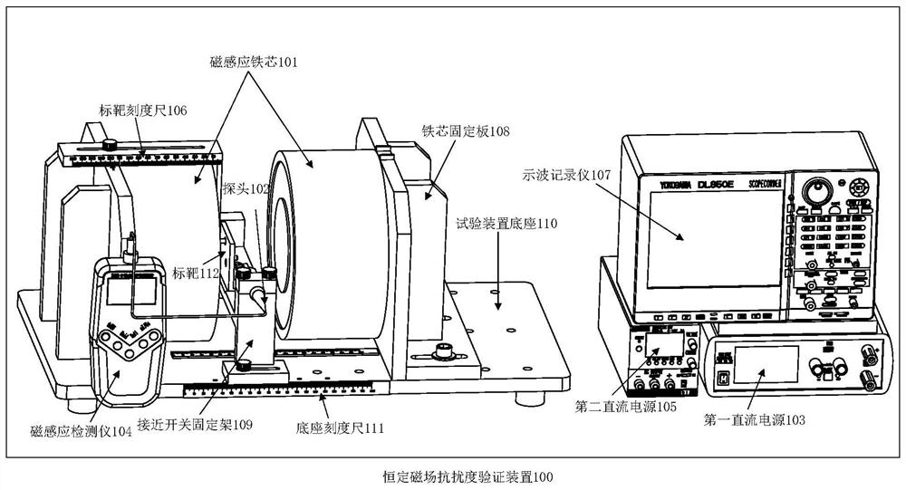
[0044] The embodiment of the present invention provides another constant magnetic field immunity verification device, see figure 2 Another constant magnetic field immunity verification device shown, the constant magnetic field immunity verification device 100 also includes: an iron core fixing plate 108, a proximity switch fixing frame 109, a test device base 110 and a target 112;

[0045] The iron core fixing plate 108 is used to fix the magnetic induction iron core 101;

[0046] Above-mentioned proximity switch holder 109 is used for fixing proximity switch;

[0047] Both the iron core fixing plate 108 and the proximity switch fixing frame 109 are installed on the test device base 110 , the test device base 110 includes a base scale 111 for measuring the distance between the magnetic induction cores 101 .

[0048] The target 112 is used to provide a moving direction for the target scale 106 , and the target scale 106 moves along the axis of the target 112 to measure the ef...

Embodiment 3

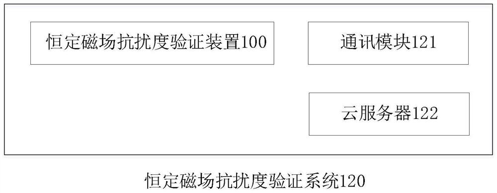
[0052] The embodiment of the present invention provides a constant magnetic field immunity verification system, see image 3 A constant magnetic field immunity verification system is shown, the constant magnetic field immunity verification system 120 includes: a communication module 121, a cloud server 122 and the above-mentioned constant magnetic field immunity verification device 100, the constant magnetic field immunity verification device 100 Communicatively connected with the cloud server 122 through the communication module 121;

[0053] The communication module 121 is used to provide a network environment for the constant magnetic field immunity verification device 100; the communication module 121 can be a WiFi (Wireless Fidelity, wireless fidelity) module or a GPRS (General Packet Radio Service, packet wireless service technology) module A sort of.

[0054] The constant magnetic field immunity verification device 100 is used to upload the verification results of the ...


PUM

PropertyMeasurementUnit
The inside diameter ofaaaaaaaaaa
Gapaaaaaaaaaa

Abstract

The invention provides a constant magnetic field immunity verification device and system. The device comprises a magnetic induction iron core, a probe, a first DC power supply, a magnetic induction detector, a proximity switch, a second DC power supply, a target calibrated scale, and an oscillographic recorder, wherein the magnetic induction iron core comprises an iron core induction coil, two ends of the iron core induction coil are connected with a positive electrode and a negative electrode of the first direct-current power source respectively, and the probe is connected with the magnetic induction detector; two ends of the proximity switch are respectively connected with positive and negative electrodes of the second direct-current power supply, and an output end of the proximity switch is also connected with the oscillographic recorder; by adjusting a current value of the first direct-current power supply and controlling magnetic induction intensity between the magnetic induction iron cores, performance and the effective action distance of the proximity switch in different constant magnetic fields are effectively verified, EN60947 5-2Annex E test standard requirements are met, a distance between the magnetic induction iron cores can be adjusted, the method can be suitable for verification of constant magnetic field immunity of most proximity switches.

Description

technical field [0001] The invention relates to the technical field of immunity verification, in particular to a constant magnetic field immunity verification device and system. Background technique [0002] Proximity switch is a detection device that can be operated without direct mechanical contact with moving parts. The main principle is to trigger the signal by inductive magnetic material and transmit it to the logic control system as the basis for judging the next step of the equipment. When an object moves towards the proximity switch and approaches it to a certain distance, the proximity switch can only "perceive" and then act. This distance is usually called "action distance", that is, the rolled metal target senses along the reference axis The distance that can cause the output signal to change when the surface moves. [0003] In the existing technology, the test and verification of proximity switches is only to verify the detection distance and corresponding perfo...

Claims


Application Information

Patent Timeline
IPC IPC(8): G01R31/327G01R1/04
CPCG01R31/327G01R31/001G01R1/0408
Inventor 雷明光聂正诚余新文张美伦
Owner DEFOND ELECTECH CO LTD
Learn More