Impeller pipeline driving structure of circulating water power generation equipment and process method of impeller pipeline driving structure

A technology of power generation equipment and drive structure, which is applied in the fields of hydroelectric power generation, mechanical equipment, engine functions, etc., and can solve problems such as large engineering volume and damage to the environment and ecology

Pending Publication Date: 2021-09-14
湖南骏能新能源有限公司
View PDF2 Cites 0 Cited by
  • Summary
  • Abstract
  • Description
  • Claims
  • Application Information

AI Technical Summary

Problems solved by technology

However, the amount of engineering is large and the damage to the environment and ecology is great

Method used


Image

  • Impeller pipeline driving structure of circulating water power generation equipment and process method of impeller pipeline driving structure
  • Impeller pipeline driving structure of circulating water power generation equipment and process method of impeller pipeline driving structure
  • Impeller pipeline driving structure of circulating water power generation equipment and process method of impeller pipeline driving structure

Examples


Embodiment 1

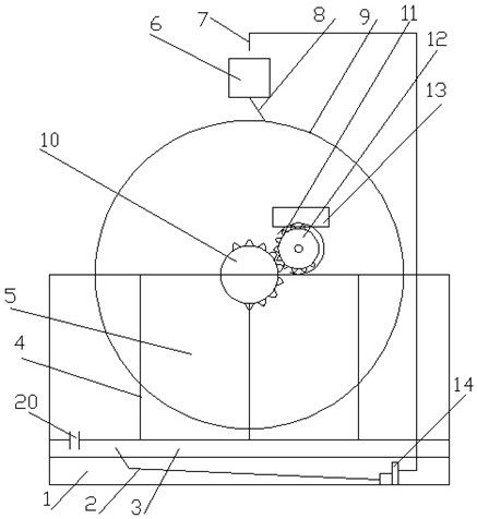
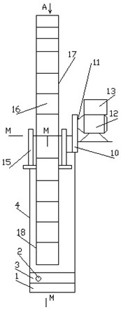
[0026] Embodiment 1, with reference to the accompanying drawings, the patent application of the present invention is a divisional application for components in the circulating hydrodynamic power generation equipment and its process method filed by the applicant on the same day, which belongs to the classified design of the original main engine. Specifically: a seat frame 4 is installed above the pool 3, an impeller 9 is installed on the seat frame 4 and a generator set 12 is installed, an electric meter box 13 is housed on the top of the generator set 12, a drive shaft 22 is arranged on the connection plate 21, and the drive shaft 22 is equipped with a drive gear 10, Generator set 12 has driven shaft 23, and driven shaft 23 is equipped with passive gear 11, and driving gear 10 meshes transmission passive gear 11, thereby drives generator set 12 work, and impeller 9 bottom faces have 1~50cm apart from pool 3 water surfaces. The periphery of the seat frame 4 is a pool 3 composed ...


PUM


Abstract

The invention discloses an impeller pipeline driving structure of circulating water power generation equipment and a process method of the impeller pipeline driving structure. The impeller pipeline driving structure of the circulating water power generation equipment is characterized in that an impeller is provided with reinforcing ribs, the reinforcing ribs are installed between a connecting disc and blades, an outer edge sealing plate and an inner edge sealing plate, the blades are installed between the outer edge sealing plate and the inner edge sealing plate for fastening, a water bucket is arranged on the top of the impeller, and an incidence pipe is arranged at the bottom of the water bucket; the incidence pipe faces the blades, a water outlet of a flushing pipe faces the water bucket, the flushing pipe is connected with a pump, the pump is connected with a pressure pipe, a port of the pressure pipe is connected into a water pool, and a circulating water opening is formed in the space between the water pool and a seat frame; and a driving shaft is arranged at the center of a connecting disc, a driving wheel is arranged at a port of the driving shaft, a driven shaft is arranged at the center of a generator set, the driven shaft is provided with a driven wheel, the driving wheel is meshed with the driven wheel, water of an incidence pipe opening rushes and presses the blades, the blades rotate along with the impeller, so that the driving wheel and the driven wheel are driven, and the driven wheel drives a generator to work. Working water flows down a circulating water port after passing through the blades and the impeller and enters the water pool to the next cycle for power generation. The structure is novel and advanced, and installation and use are convenient.

Description

technical field [0001] The invention belongs to electric equipment, in particular to an impeller pipeline driving structure and a process method of circulating hydropower generating equipment. Background technique [0002] The power generation of the transmission hydroelectric generating set is to generate electricity by using high mountain water or river dams to store water. These technical methods are simple and low in cost. However, the amount of engineering is large and the damage to the environment and ecology is great. Existing comparative document 1, application number: CN202010944939, name of invention: a wind turbine impeller overspeed protection device and control method, including a wind turbine body, a generator is installed inside the wind turbine body, and one side of the generator passes through the machine. The shaft is fixedly connected to the planetary gear speed-up box, and the side of the planetary gear speed-up box passing through the wind turbine body ...

Claims


Application Information

Patent Timeline
IPC IPC(8): F03B13/06F03B1/00
CPCF03B13/06F03B1/00F05B2220/706F05B2260/4031Y02E60/16Y02E10/20
Inventor 梁建新梁源彭章发
Owner 湖南骏能新能源有限公司
Why Eureka
Try Eureka