Online laser marking device and method for hot-rolled steel billet

A technology of laser marking and billet, applied in the field of billet continuous casting and rolling, laser marking, and iron and steel production, it can solve the problems of expensive high temperature resistant paint, ineffective marking and erasing.

Pending Publication Date: 2021-09-14
安阳睿恒数控机床股份有限公司
View PDF0 Cites 2 Cited by
  • Summary
  • Abstract
  • Description
  • Claims
  • Application Information

AI Technical Summary

Problems solved by technology

[0006] The current automatic marking machine mainly has three types of spraying numbers, among which, the first is to mark the firing pin by mechanical impact, which is generally not used by manufacturers because it may affect the quality of the billet; the second is to use high temperature resistant water-based milky white paint Spraying through the nozzle, due to the high temperature, the nozzle cannot be close to the billet, and the width of the stroke is required to be less than 5mm. It is difficult to ensure the quality of the spray in actual processing. At the same time, the nozzle is easily damaged, and the high temperature resistant coating is expensive, which also limits the application; the third is to use arc atomization. The aluminum method sprays aluminum directly onto the billet, and the difficulties encountered in actual processing are very similar to the second method above
The numbering equipment currently used is expensive. The cost of using a numbering machine to mark a million tons of steel is as high as 2 million yuan, which is expensive and pollutes seriously. Therefore, the numbering of steel billets still needs to be solved from the printing process.
[0007] Laser marking is a mature process technology. Compared with the spraying machine, it can solve the problem of spraying atomization, but it is difficult to directly apply it to billet marking
The difficulty is that, firstly, due to the high temperature and harsh environment of the steel billet, the laser marking head must be kept away from the steel billet, and the focal length that the current laser marking machine can use is generally only 100-250mm. Second, the current laser marking depth is only on the order of microns, and the mark cannot be effectively maintained in the subsequent production process of the billet, and it is easy to be erased by the subsequent process
Moreover, the currently used laser marking technology is generally based on the information required by the galvanometer to scan and control the formation of the beam. In practice, it is difficult for the galvanometer to work stably in harsh environments; at the same time, the laser power that the galvanometer can withstand is limited, which is different from that of steel billets. Marking requires high laser power to achieve high speed and deep marking form contradiction

Method used


Image

  • Online laser marking device and method for hot-rolled steel billet
  • Online laser marking device and method for hot-rolled steel billet
  • Online laser marking device and method for hot-rolled steel billet

Examples


Embodiment 1

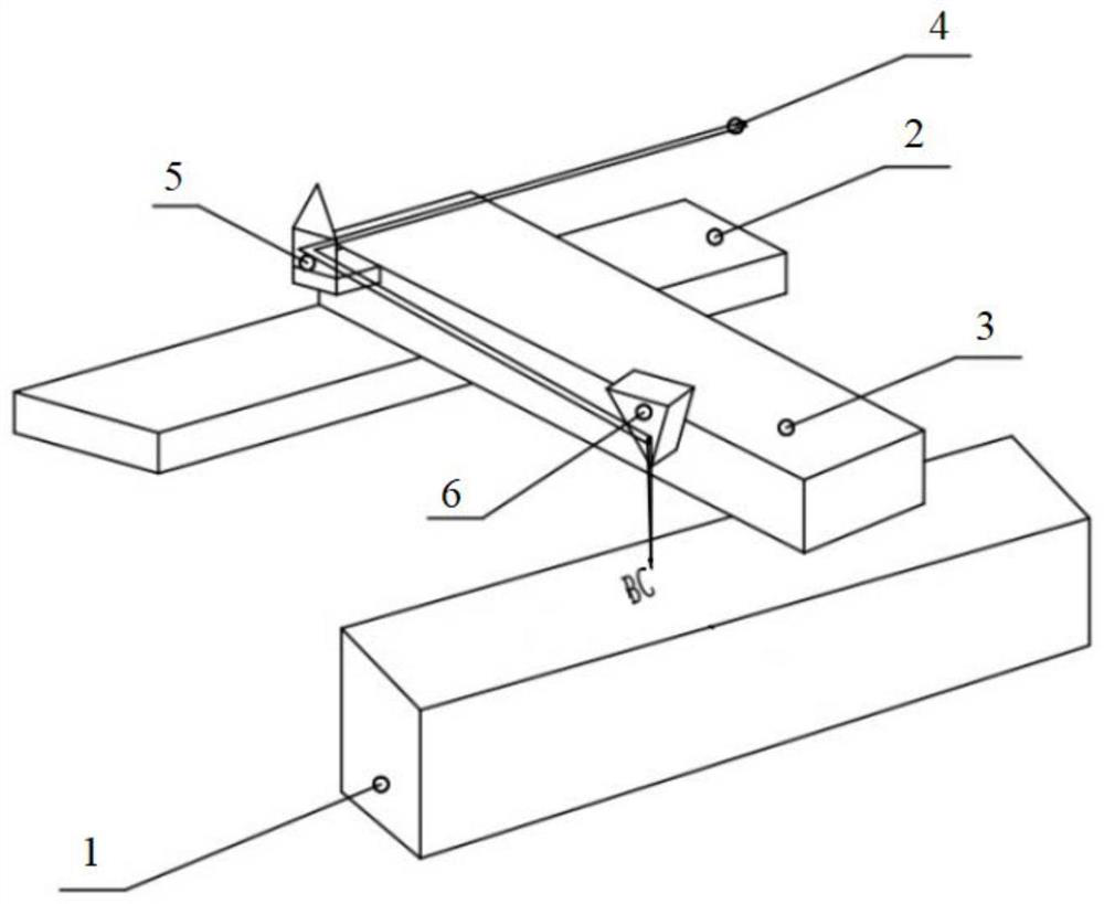
[0046] This embodiment provides a hot-rolled billet online laser marking device and method, such as figure 1 As shown, the device is set above the hot-rolled steel billet production line, and can perform laser marking on the hot-rolled billet 1 online. The device includes: a laser, a light guide mechanism, a focusing mechanism, a two-dimensional linear motion mechanism and a control unit. The two-dimensional linear motion mechanism includes a Y guide rail 2 and an X guide rail 3, wherein the X guide rail 3 is installed on the Y guide rail 2, and the two are arranged perpendicularly, and the X guide rail can move along the Y direction with the Y guide rail 2, The light guiding mechanism and the focusing mechanism are installed on the X guide rail 3, and can move with it under the drive of the two-dimensional linear motion mechanism, wherein the light guiding mechanism is used to guide the irradiation direction of the laser beam 4 emitted by the laser, and the focusing mechanism ...

Embodiment 2

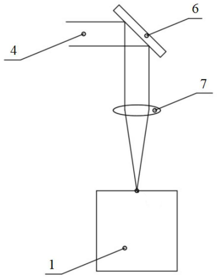
[0071] This embodiment provides a hot-rolled billet online laser marking device and method, such as Figure 7 As shown, the device is set above the hot-rolled steel billet production line, and can perform laser marking on the hot-rolled billet 1 online. The device includes: a laser, a light guide mechanism, a focusing mechanism, a two-dimensional linear motion mechanism and a control unit. The two-dimensional linear motion mechanism includes a Y guide rail 2 and an X guide rail 3, wherein the X guide rail 3 is installed on the Y guide rail 2, and the two are arranged perpendicularly, and the X guide rail can move along the Y direction with the Y guide rail 2, The light guiding mechanism and the focusing mechanism are installed on the X guide rail 3, and can move with it under the drive of the two-dimensional linear motion mechanism, wherein the light guiding mechanism is used to guide the incident direction of the laser beam 4 emitted by the laser, and the focusing mechanism is...


PUM


Abstract

The invention provides an online laser marking device and method for a hot-rolled steel billet, and relates to the field of steel production and laser marking. The device comprises a laser, a light guide mechanism, a focusing mechanism, a two-dimensional linear motion mechanism and a control unit, wherein the light guide mechanism is used for guiding the incident direction of laser beams, the focusing mechanism is used for focusing the laser beams into light spots and guiding the light spots to the surface of the steel billet to mark the surface of the steel billet, and the control unit is used for controlling the two-dimensional linear motion mechanism to move according to marking information. The method comprises the steps of mounting, cleaning, positioning, focusing, marking and the like. After the above device is mounted on a production line, an oxide layer on the surface of the steel billet is cleaned, the position and height of the steel billet are determined through a camera and the like, the focusing height of the steel billet is adjusted according to the height, the marking information formed by connecting a plurality of parallel lines or rotating light spots is marked on the surface of the steel billet by using the focused light spots, and air blowing and water cooling are carried out in the marking process, so as to meet the operation requirement in a high-temperature severe environment, and the stability and reliability of the device are ensured.

Description

technical field [0001] The invention relates to the technical fields of iron and steel production, billet continuous casting and rolling, and laser marking, in particular to an online laser marking device and method for a hot-rolled billet. Background technique [0002] In the automatic production process of iron and steel metallurgical enterprises, in order to carry out quality tracking management and provide a traceability basis for the steel production process, it is necessary to timely add marks on the steel during the processing process—a set of marks composed of letters and numbers. Furnace number, tank number, steel type code, stream number and billet serial number, etc. Once a quality problem occurs, the date of production, furnace number, batch number, corresponding material status and other relevant information can be traced according to this group of letters and numbers, providing reliable reference materials for finding and solving problems. [0003] In the iron...

Claims


Application Information

Patent Timeline
IPC IPC(8): B23K26/362B23K26/08B23K26/064B23K26/146B23K26/14B23K26/60
CPCB23K26/362B23K26/0876B23K26/0643B23K26/0648B23K26/146B23K26/14B23K26/60B23K2101/007B23K2103/04
Inventor 杜建伟王阳阳
Owner 安阳睿恒数控机床股份有限公司
Why Eureka
Try Eureka