Laser-based airport runway foreign matter recognition device and method

An airport runway and identification device technology, applied in the field of optoelectronic information, can solve problems such as low efficiency, inability to use airport runway for transportation, and difficult foreign object detection.

Pending Publication Date: 2021-09-10
王华
View PDF2 Cites 0 Cited by
  • Summary
  • Abstract
  • Description
  • Claims
  • Application Information

AI Technical Summary

Problems solved by technology

In the past, most of the identification of FOD on the airport runway relied on manual regular inspections and human eyes to search for foreign objects. When the environment of the airport runway is harsh, especially at night or in low visibility conditions, it is difficult to perform accurate foreign object detection. The reliability is poor and time-consuming and labor-intensive.
At present, for the identification of FOD on the airport runway, a Chinese invention patent with the publication number CN111562576A proposes a foreign object detection system and method on the airport runway. The patent application uses radar scanning and image processing to identify FOD in the area, but this method is not accurate enough for small foreign objects. Low and complex operation, low efficiency
In addition, the Chinese utility model patent with the notification number CN 208255440 U proposes an airport runway FOD detector, which uses a laser mounted on a trolley to identify foreign objects, but the biggest weakness of this kind of detector is that it needs to be detected during the detection process. Interruption of traffic, unusable for transportation on busy airport runways, resulting in fewer flights and economic loss

Method used


Image

  • Laser-based airport runway foreign matter recognition device and method
  • Laser-based airport runway foreign matter recognition device and method
  • Laser-based airport runway foreign matter recognition device and method

Examples


Embodiment Construction

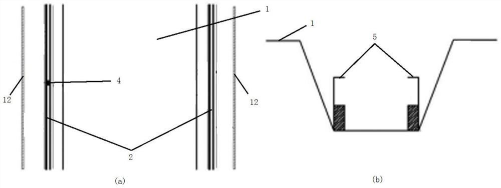
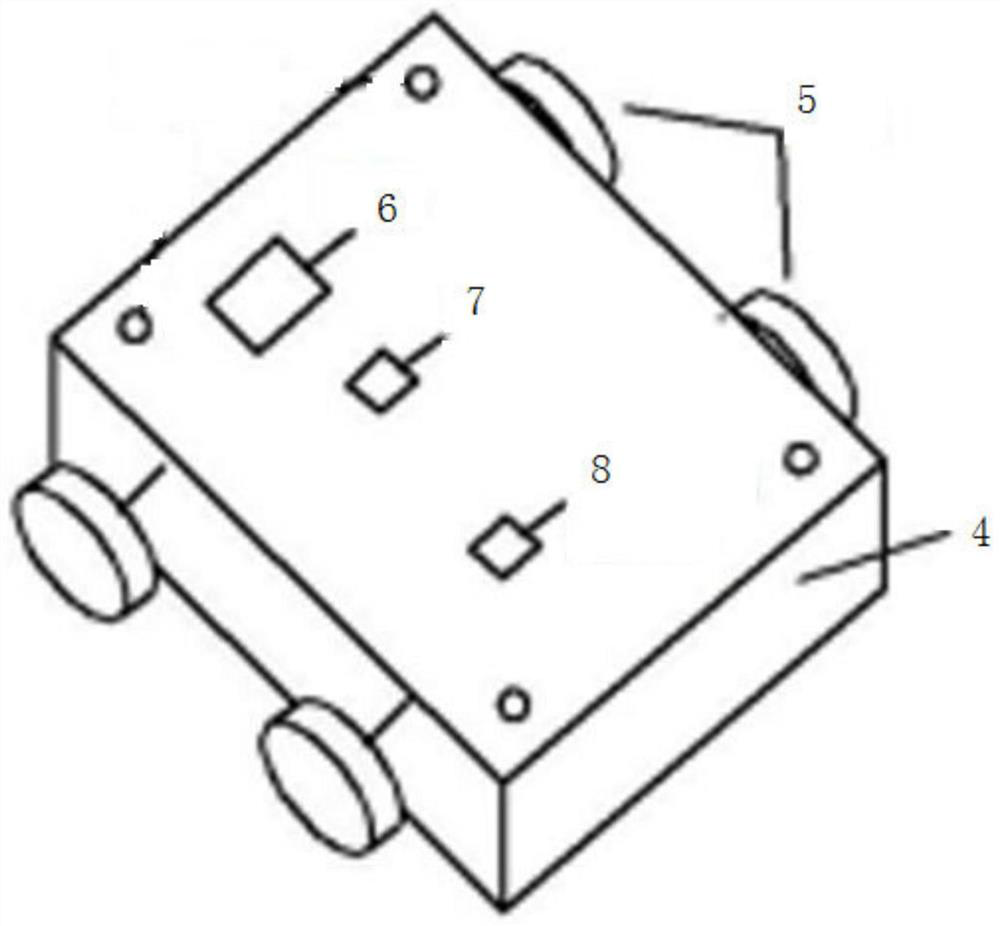
[0030] see Figure 1 to Figure 3 , In a preferred embodiment of the present invention, a laser-based airport runway foreign object recognition device includes a track 3 system, a base 9, a laser sensor 10, a reflective wall 12, DTU equipment, and a terminal platform. The track 3 system is arranged on one side of the airport runway 1, and the other side of the airport runway 1 is provided with a reflective wall 12; the track 3 system is arranged parallel to the airport runway 1, and the track 3 system includes a track 3 groove 2 , track 3, pulley trolley 4, power assembly 6, radio control chip 7 and Beidou system locator 8, described track 3 groove 2 is opened on the side of airport runway 1, and its notch is flush with the road surface of described airport runway 1, A track 3 is arranged at the bottom of the groove 2 of the track 3, and a pulley trolley 4 is rollingly installed on the track 3, and the pulley trolley 4 does not protrude from the road surface of the airport runw...


PUM


Abstract

The invention provides a laser-based airport runway foreign matter recognition device and method, and the device comprises a track system which is disposed at one side of an airport runway, and the other side of the airport runway is provided with a reflection wall. The track system is parallel to an airport runway and comprises a track groove, a track is arranged at the groove bottom of the track groove, a pulley trolley is installed on the track in a rolling mode, the pulley trolley does not protrude out of the pavement of the airport runway, a power assembly, a radio control chip and a Beidou system positioner are installed on the pulley trolley, and the power assembly is connected with the radio control chip. The radio control chip and the Beidou system positioner are respectively and wirelessly connected with the terminal platform; and the base is mounted on the trolley, the laser sensor and the DTU equipment are mounted on the base, and the laser sensor is wirelessly connected with the terminal platform through the DTU equipment. Based on the identification method provided by the device, the millimeter-level foreign matter can be identified, the identification precision is high, the efficiency is high, and meanwhile, the influence on airport traffic is small.

Description

technical field [0001] The invention relates to the field of photoelectric information technology, in particular to a laser-based foreign object identification device and identification method on an airport runway. Background technique [0002] FOD is the abbreviation of Foreign Object Debris, which translates as some kind of foreign matter that may damage the aircraft. The detection of foreign objects (FOD) on the airport runway is very important for the safe operation of the airport. The Safety Technology Center of the Civil Aviation Administration of the Civil Aviation Administration of China issued a FOD prevention manual in 2009, which proposed the necessity of a FOD detection system, and pointed out that the current airport in my country Monitoring of FOD is still incomplete. In the past, the identification of FOD on the airport runway mostly relied on manual regular inspections and human eyes to search for foreign objects. When the environment of the airport runway is...

Claims


Application Information

Patent Timeline
Patent Type & Authority Applications(China)
IPC IPC(8): G01S17/04G01S17/88G01S19/42G08C17/02
CPCG01S17/04G01S17/88G01S19/42G08C17/02
Inventor 王华王龙林李俊毅
Owner 王华
Why Eureka
Try Eureka