Waterproof plugging structure for roof pipeline and construction method

A construction method and roof structure layer technology, applied in the direction of roof, roof covering layer, building structure, etc., can solve the problems of affecting the roof waterproof effect, peeling of coiled materials, rainwater infiltration, etc.

Active Publication Date: 2021-09-10
CHINA MCC17 GRP
View PDF6 Cites 3 Cited by
  • Summary
  • Abstract
  • Description
  • Claims
  • Application Information

AI Technical Summary

Problems solved by technology

[0002] In the construction process of roof pipe waterproofing, waterproof mortar is usually used to seal the gap between the casing and the pipe, the waterproof coiled material is turned over to the steel casing, and the upper opening is sealed with sealing paste. It is difficult to attach the mortar on the surface of the waterproof membrane, and the waterproof membrane is exposed for a long time, causing the membrane to fall off, and the rainwater seeps into the roof structure layer, affecting the overall waterproof effect of the roof

Method used


Image

  • Waterproof plugging structure for roof pipeline and construction method
  • Waterproof plugging structure for roof pipeline and construction method
  • Waterproof plugging structure for roof pipeline and construction method

Examples


Embodiment 1

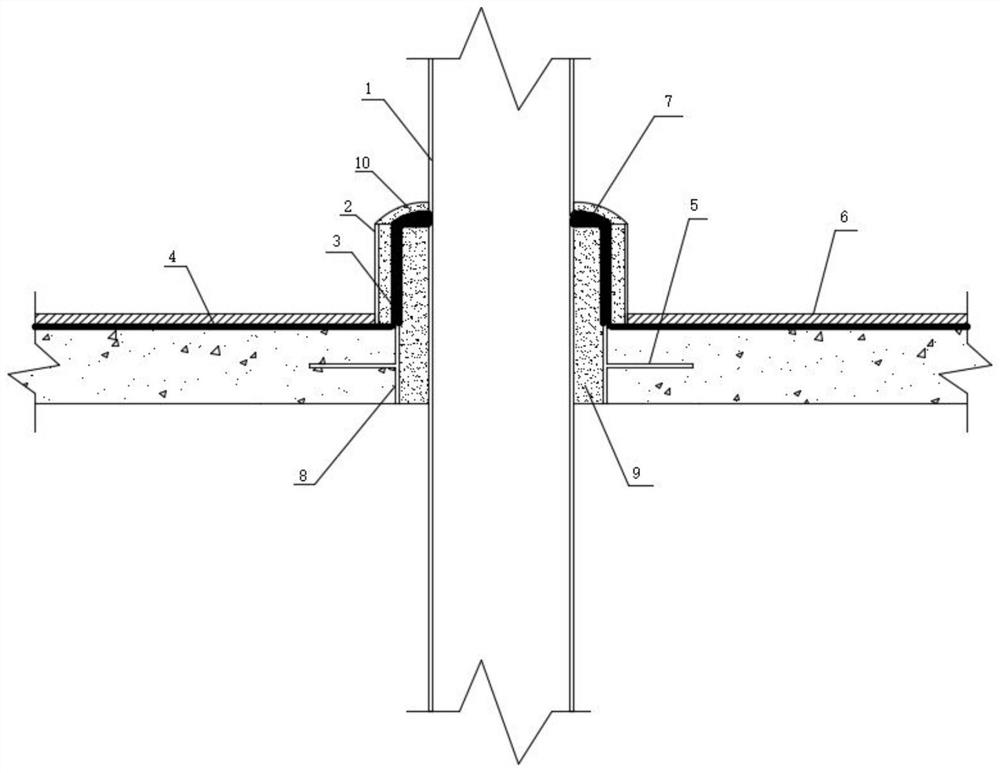
[0025] Such as figure 1 As shown, a waterproof sealing structure for the roof outlet pipeline includes a steel sleeve 8 (set coaxially with the roof outlet pipeline 1) embedded in the roof structure layer and equipped with a water stop ring 5, poured on the steel sleeve 8 and the polymer waterproof mortar between the roof pipe 1-9, the leveling layer 4 above the roof structure layer, the waterproof coiled material 3 bonded to the upper surface of the leveling layer 4 and the outside of the steel sleeve 8, sealed in the The waterproof membrane 3 and the asphalt-based sealant 7 on the top of the polymer waterproof mortar are set on the outer side of the waterproof membrane 3 and the galvanized pipe 2 with a gap between the inner wall and the waterproof membrane 3 is reserved, and poured on the galvanized pipe 2 and waterproof Polymer waterproof mortar 2 10 between the rolls 3 and covering the top of the asphalt-based sealant 7 . The waterproof coiled material 3 is protected by ...

Embodiment 2

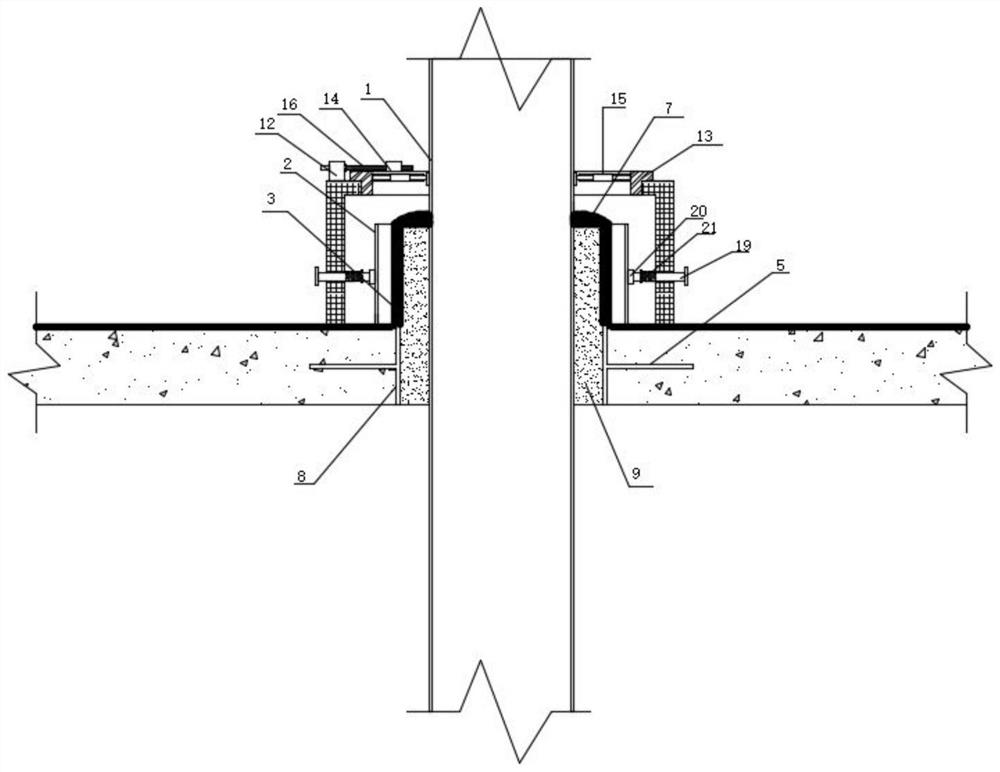
[0028] Embodiment 2: as figure 2 and image 3 As shown, a further preferred solution on the basis of Embodiment 2: the construction method of the above-mentioned embodiment includes the following steps: first, the steel casing 8 is pre-embedded inside the roof structure layer, and the roof pipe 1 is installed and located at the bottom of the roof structure layer. formwork at the bottom of the slab, spread mortar on the surface of the roof structure layer as a leveling layer 4, and spread and bond waterproof membrane 3 on the leveling layer 4, and wrap the steel casing 8 and turn it over by the top of the steel casing 8 Wrap the top of the steel casing 8, then pour polymer waterproof mortar-9 between the roof outlet pipe 1 and the steel casing 8, and then cover the top of the polymer waterproof mortar-9 and the waterproof membrane 3 for asphalt-based sealing Paste 7, set galvanized pipe 2 on the outside of steel casing 8, and pour polymer waterproof mortar 2 10 between galvan...

Embodiment 3

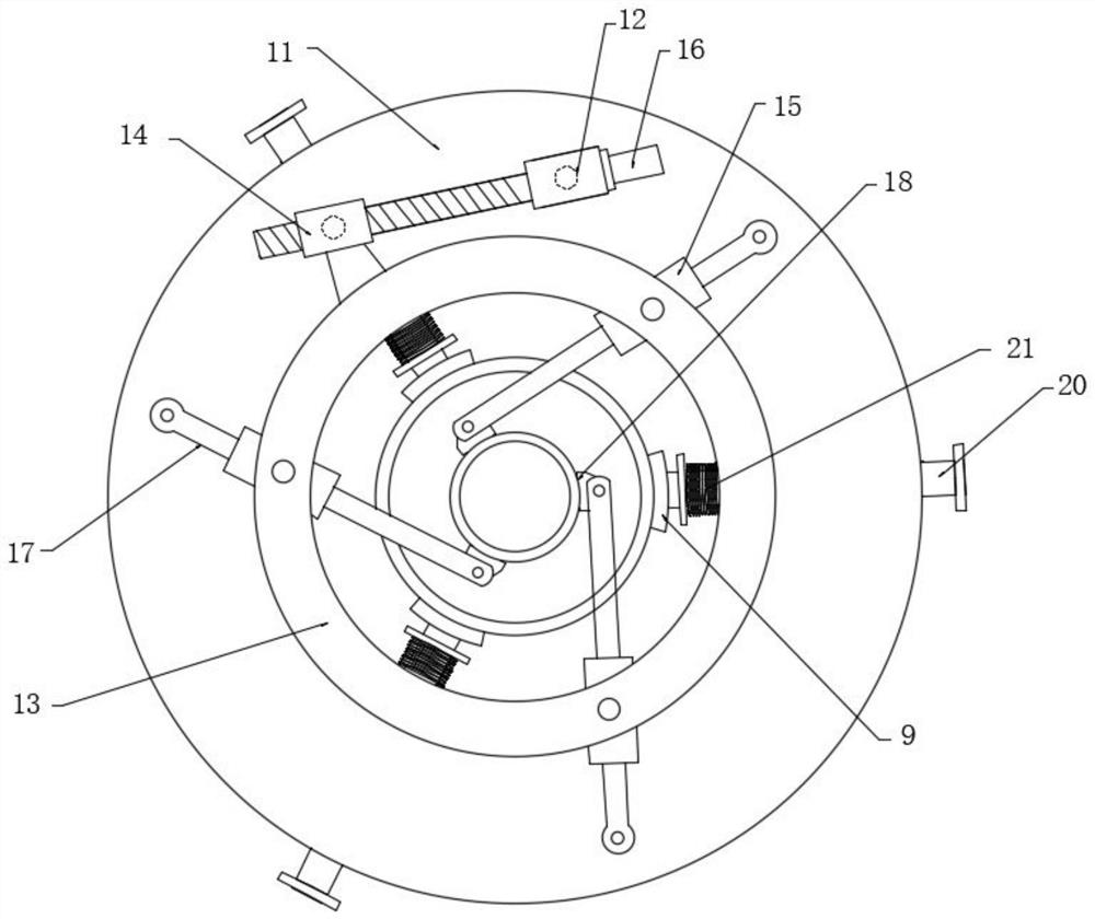
[0033] Embodiment 3: as figure 2 and image 3 As shown, a further preferred solution on the basis of Example 2: the installation of the galvanized pipe 2 and the working steps of pouring the polymer waterproof mortar 2 10 are as follows:

[0034] First place the galvanized pipe 2 on the outside of the steel casing 8, then install the mounting frame 11 on the outside of the galvanized pipe 2, and clamp the galvanized pipe 2 through the positioning claw 20, and then adjust the rotation by adjusting the adjusting screw 16 The positions of the seat one and the rotating seat two drive the active part 13 to rotate relative to the mounting frame 11, and the rotating seat will rotate accordingly, and the position of the driven part 17 will also change with the rotation, and the jaws 18 on the driven part 17 will automatically rotate. Clamp the roof outlet pipe 1, at this time, the galvanized pipe 2 is automatically coaxial with the roof outlet pipe 1 and the steel casing 8, pouring ...


PUM


Abstract

The invention discloses a waterproof plugging structure for a roof pipeline and a construction method, and belongs to the technical field of building construction. The waterproof plugging structure comprises a steel sleeve, first polymer waterproof mortar, a leveling layer, a waterproof coiled material, asphalt-based sealant, a galvanized pipe and second polymer waterproof mortar, wherein the steel sleeve is pre-buried in a roof structure layer and provided with a water stop wing ring; the first polymer waterproof mortar is poured between the steel sleeve and the roof pipeline; the leveling layer is laid on the roof structure layer; the waterproof coiled material is bonded to the upper surface of the leveling layer and the outer side of the steel sleeve; the asphalt-based sealant is sealed at the top of the waterproof coiled material and the top of the polymer waterproof mortar; the waterproof coiled material is sleeved with the galvanized pipe; a gap is reserved between the inner wall of the galvanized pipe and the waterproof coiled material; and the second polymer waterproof mortar is poured between the galvanized pipe and the waterproof coiled material and covers the top of the asphalt-based sealant. The waterproof effect of the roof pipeline is achieved through the measures of effectively plugging the space between the steel sleeve and the roof pipeline, turning the waterproof coiled material upwards to the top face of the steel sleeve, effectively protecting the waterproof coiled material turned to the steel sleeve and the like, and the pipeline is not leaked.

Description

technical field [0001] The technical field of building waterproof construction that the present invention relates to, in particular, relates to a waterproof sealing structure and construction method for a roof outlet pipeline. Background technique [0002] In the construction process of roof pipe waterproofing, waterproof mortar is usually used to seal the gap between the casing and the pipe, the waterproof coiled material is turned over to the steel casing, and the upper opening is sealed with sealing paste. It is difficult to attach the mortar on the surface of the waterproof membrane, and the long-term exposure of the waterproof membrane will cause the membrane to fall off, and the rainwater will penetrate into the roof structure layer, affecting the overall waterproof effect of the roof. Contents of the invention [0003] The purpose of the present invention is to solve the deficiencies in the prior art, so a waterproof sealing structure and construction method for the...

Claims


Application Information

Patent Timeline
Patent Type & Authority Applications(China)
IPC IPC(8): E04D13/14E04D13/16
CPCE04D13/14E04D13/1407E04D13/16
Inventor 丁健华惠智勇
Owner CHINA MCC17 GRP
Why Eureka
Try Eureka